Intro
This is a continuation to another article, check it out!
Fixing my High School Diploma Project
When I graduated High School, every student had to substain a final oral exam. As I attended a technical school, the main part of the exam was the exposition of a project, designed and built by the student, followed by questions on other subjects and extracurricular activities and projects.
The teachers had to assign a project to each student, but my teachers where open to ideas from us (for kindess or lazyness I can’t tell, but I tend to the latter). I decided to build a function generator, and my teachers allowed me to. A function generator is a electronics lab instrument used to generate signals of different waveforms (say, sinusoidal, square, triangle, sawtooth…) with different frequencies, amplitude, dc offset.
Now, I’m not really an analog guy, and High School left me with some pretty big holes in the knowledge of electronics. Plus our labs at school were full of old, analog function generators, so building yet another one wouldn’t be anything particularly interesting. So I decided to build a digital function generator, based on a microcontroller (in this case a Teensy 3.5) commanding a DAC (Digital-Analog Converter, the Teensy 3.5 has two on board). I went with the Teensy 3.5 because that was what we were using at the time in the robotics lab and since we run low on time, I decided to stick with what I knew well.
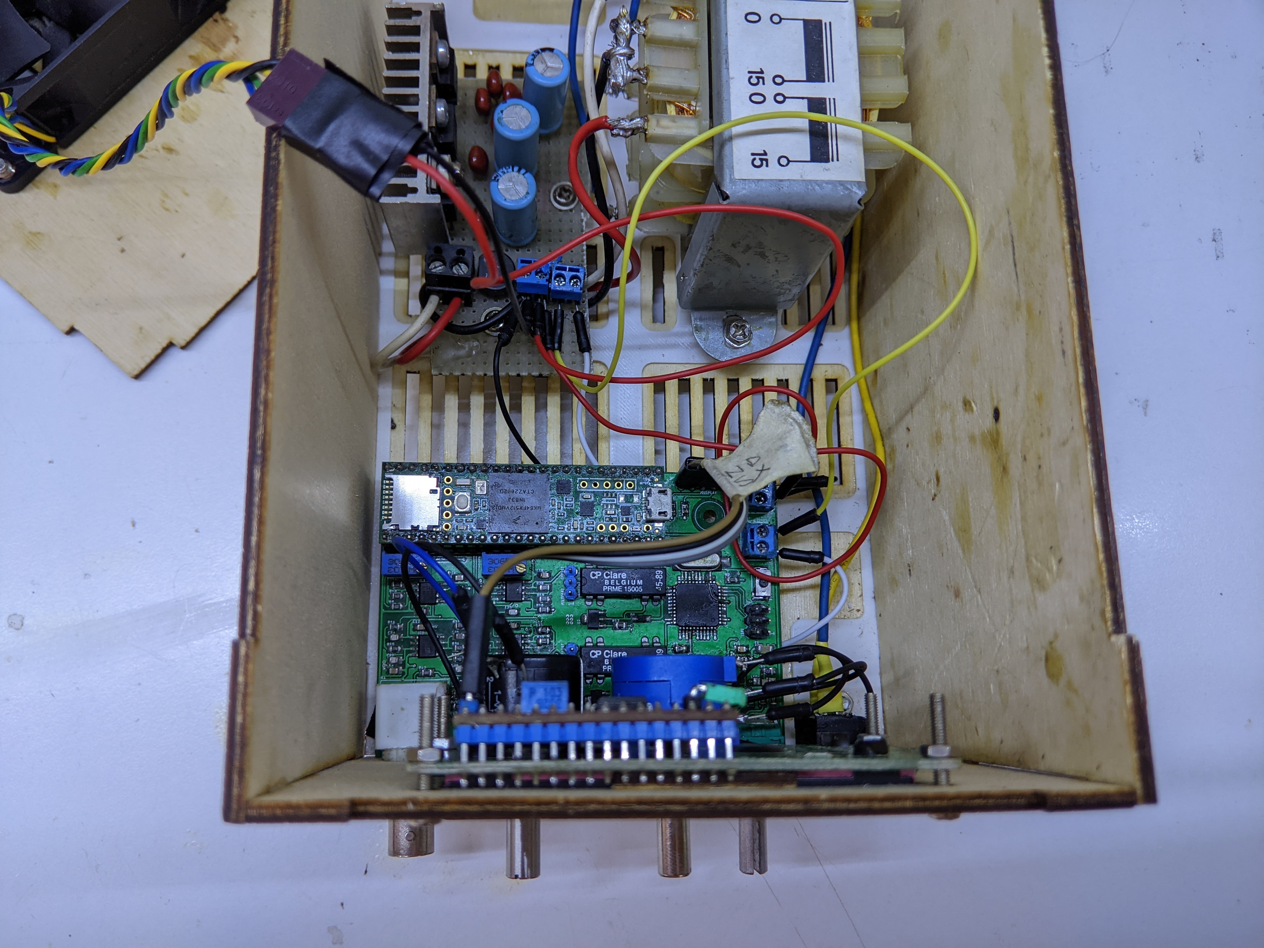
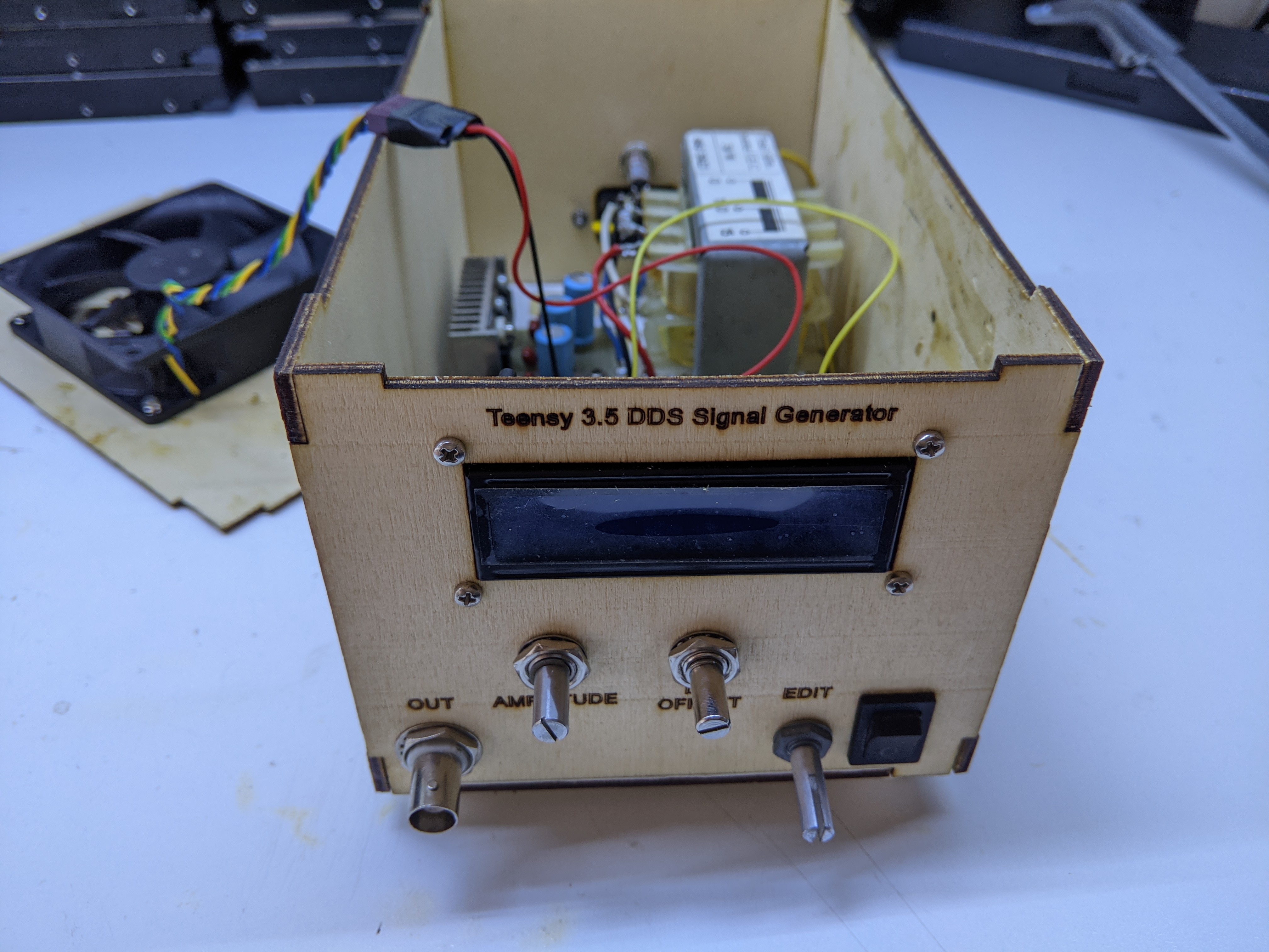
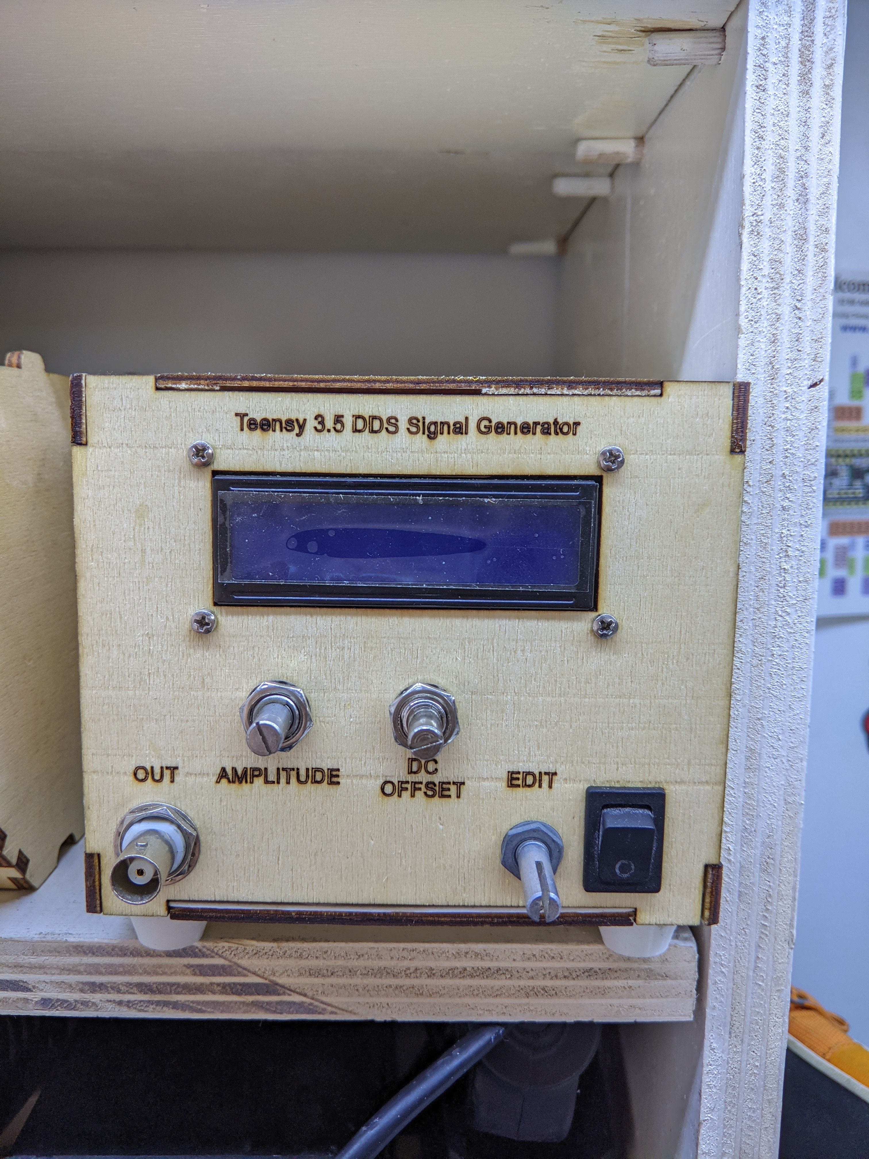
I think I did pretty well with the project. I designed the circuits and the PCB myself, wrote the firmware for microcontroller and overall ended up with a function generator that could output sine and square waves up to 1MHz. I open-sourced it under the GPLv3, and you can check it out on GitHub. In the repo is also an explanation of the design choices I made at the time. Alongside the main PCB, I also built a little power supply board using a transformer and a couple 78xx/79xx ICs to get 5V, 12V, -12V power lanes for the board. I got a friend of mine from the robotics lab to also design me a case to make out of laser-cut 4mm plywood.
Issues
The exam was a success, the teachers really liked my project and so I did. Yet during the presentation I came across a few problems I would have liked not to, here’s a list of them.
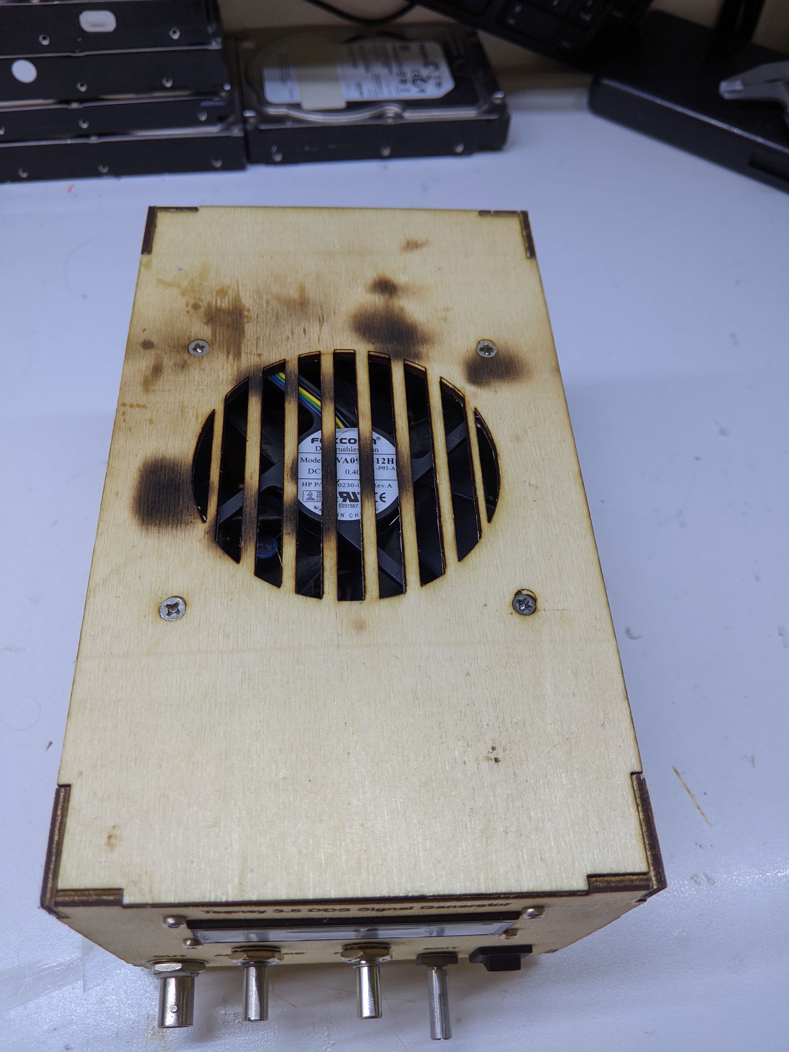
I mounted a 80mm fan to the case to blow air on the components and prevent them from overheathing. Much more a preventive measure that something actually needed. When the fan was running, the output waveform from the generator got all distorted, sometimes disappearing completely.
Managing the amplitude and the offset of the wave was an absolute pain. The controls seemed counter-intuitive and also seemed to interfere with each other.
The information reported on the LCD Screen about amplitude and DC offset were always wrong.
Let’s go in order and see how I fixed these issues.
The Fan
Actually this one I’ve know since the exam day itself. When I noticed it during the exam, I immediately explained a possible reason it was happening.
The transformer I was using was a little 30Vpp 6VA unit, where VA means Volt-Ampere, a.k.a Watt. This means the transformer can provide at most 6VA/30V=0.5A of current. With the fan alone sucking 0.4A at 12V (nominal, probably more), the voltage on the 12V rail dropped enough to be a problem for the OpAmps in the circuit. The 5V rail was not touched by this, despite being derived from the 12V rail.
I couldn’t notice this problem during my tests because I was using an ATX PC PSU, which can output plenty of current for my microcontroller and a fan.
Using a beefier transformer solved this problem, yet it introduced the problem of having the design a new case to house it.
Amplification + offset stage
I used the DAC to only generate a low-voltage signal. A later stage with OpAmps took care of amplificating this low-voltage signal up in the power supply (-12V, 12V) range and adding an eventual DC Offset to the signal, both set with two potentiometers on the board.
First problem I noticed: the potentiometers were logaritmic and not linear! That’s surely a reason controlling them was a pain. At the time I honestly didn’t even know there where both linear and logarithmic potentiometer. I replaced them with two nice multi-turn linear potentiometers (yet another reason the chassis needed a redesign)
Second problem I noticed: It’s all wrong!
By probably misinterpreting what a teacher told me, but surely forgetting basic OpAmp theory, I
designed the Amplification+Offset stage like so.
An OpAmp usign negative feedback basically tries to modify it’s output so that the different between the inverting (-) and non inverting input (+) is 0. By designing the circuit like that I basically set the OpAmp in a difference amplifier configuration (and also set myself up for trouble in the reading stages, read down for that)
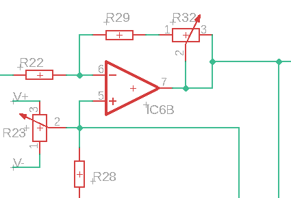
The solution is redesigning the circuit like this instead, basically putting the OpAmp in a inverting summer configuration. Since I matched the resistor ratios, the output will be ${}over{}$.

I applied this fix by cutting a trace on the PCB and soldering a couple additional 1k resistors, one connecting the potentiometer to the inverting input of the OpAmp, the other connecting the non inverting input to ground. Here you can see it somewhat working
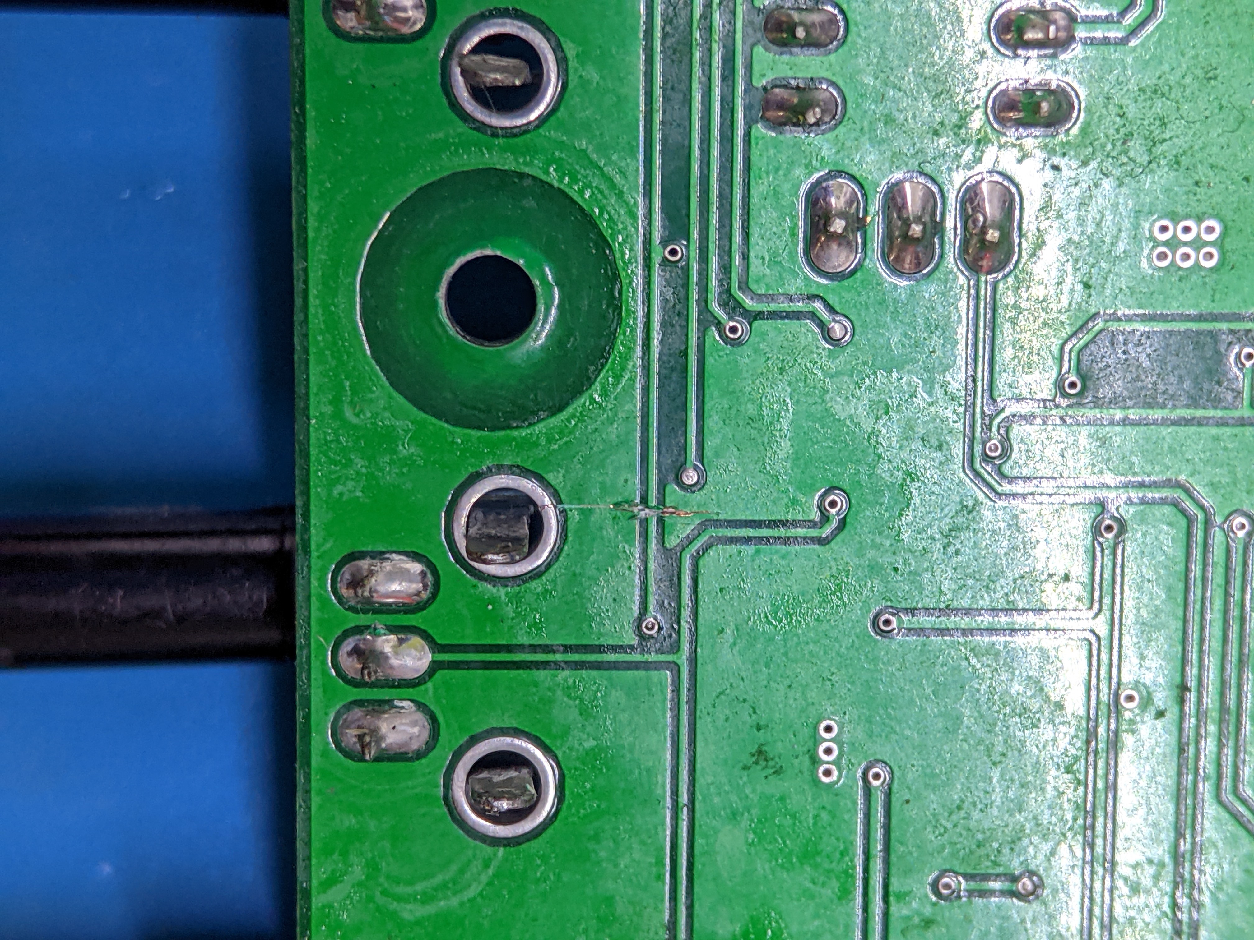
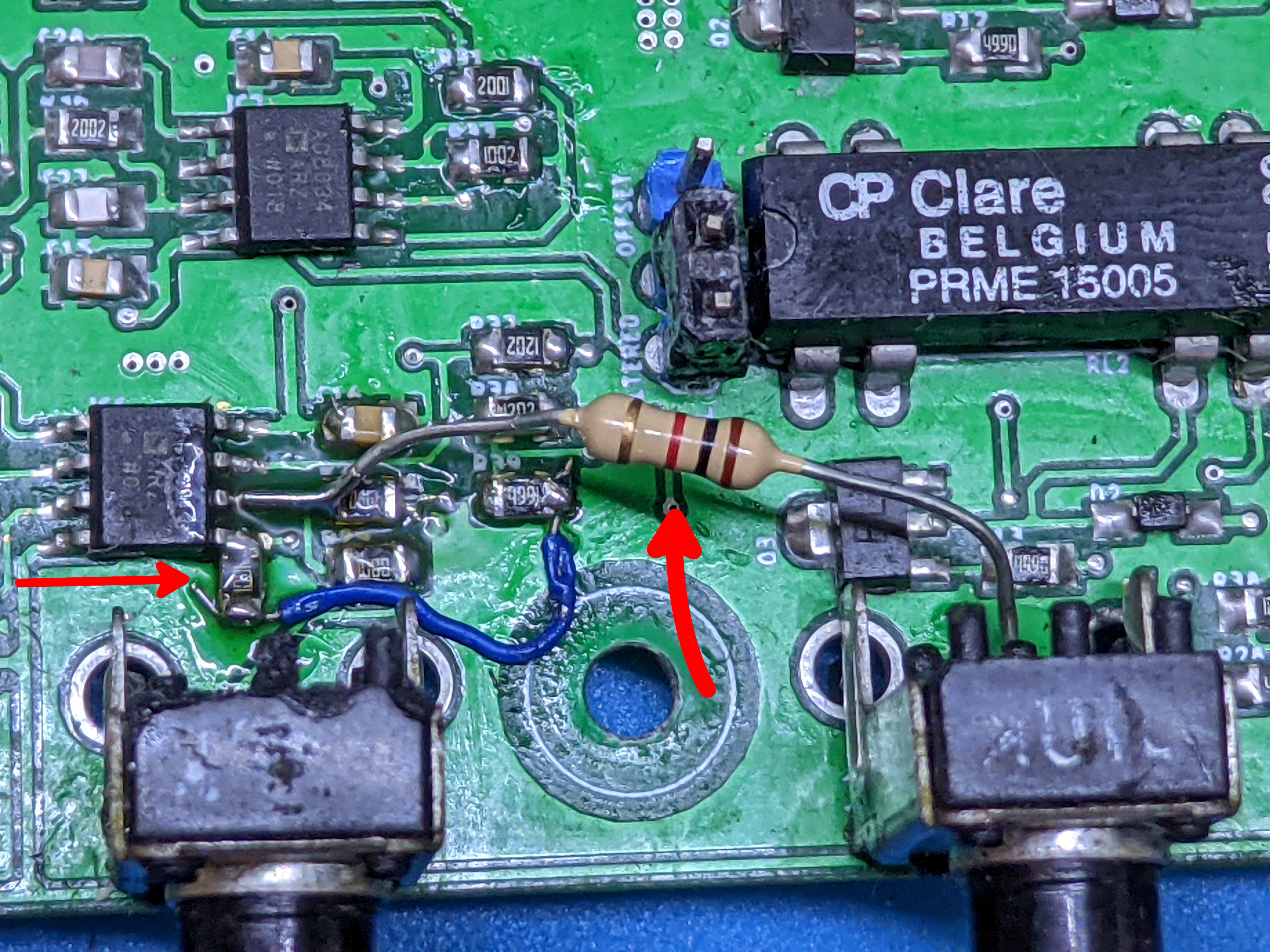
Do you see the problem with this? There’s actually two:
Configuring the OpAmp this way, the output is
while it really should be
A solution (and probably the correct way to achieve this) would be to have separate amplification and offset stages, the latter following the former.
Using a potentiometer as a voltage divider is not a stiff voltage reference. Moreso given that the potentiometer is 100k and the resistors is 1k. As a good rule of thumb for using voltage dividers as voltage references, the impedance of the load should be at least an order of magnitude (10 times) bigger than the bottom resistor. There are obviously some positions of the potentiometer for which this doesn’t happen, also considering that I have two different circuits connected to the same voltage reference by only a low-value resistor.
Peak voltage/offset reading
As said in the original article, the Teensy 3.5 is only ever used to pilot the DACs. The UI gets taken care of by a secondary Atmega 32u4, which also reads back information (amplitude, dc offset) about the waveform from the respective stage, to display it on a LCD screen.
Obviously these are signals that swing in the range (-12, 12V) and the ADC of the 32u4 only tolerates signals in the [0, 5V] range.
As you will read, both of the problems can easily be solved if I had to separate stages for amplification and offset.
These are the two circuits for (left) offset reading and (right) peak voltage reading. Let’s start with the latter.

Peak voltage
My idea at the time was to:
- Take the final waveform
- Subtract the dc offset from it (which was just added)
- Use a simple diode-capacitor peak-detector
- Scale the output by a factor of 5
- Offset it by 2.5V
These are really a lot of extra steps for something so simple. And I made the same mistake as before (and it won’t even be the last time in this post)!
While the idea itself is not so bad (if you don’t consider the -again- wrong opamp configuration) this can be solved more easily.
At first I tried to fix it using the a non-invering summer configuration for the opamp, and decoupling the impedance of the dc offset potentiometer with a voltage follower OpAmp. It worked, but the OpAmps I used had some problems when the signal amplitude got near -12V or 12V. Changing the power supply board and adding 3 more OpAmps (one for each opamp stage that used the dc offset value) is out of the question: I want to keep the fixes simple and contianed within the original PCB as much as possible. Furthermore the output of a given OpAmp in a non-inverting configuration is always >1, which doesn’t fit my usecase at all
What worked was instead using a 100nF capacitor after the amplification stage, which blocks all dc signals (like the dc offset) and only lets through ac signals (like the waveform). After that, the signal can be scaled to be in the [0V, 5V] range with appropriately selected resistors. Finally a diode-capacitor peak-detector.
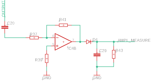
This works really good, and to implement this fix I only had to rearrange a couple of components on the PCB, cut a trace, and change the 32u4 firmware to account for the new resistor values.
However, the simple diode-capacitor peak-detector cannot detect signals below the diode barrier voltage of about 0.4V (I am using a schotky diode). This can be solved by using a peak-detector with OpAmps instead, which account for the voltage drop on the diode.
DC Offset reading
The idea is similar to the peak detector and the mistakes were the same:
- Take the dc offset as given by the potentiometer
- Scale it by 1/5
- Offset it by +2.5V
Since the mistakes are the same as explained before I won’t repeat myself (wrong configuration + potentiometer is not a stiff voltage reference + resistor values). The problem in this case is that I really don’t have a way to fix it without completely butchering the PCB, so I will leave it as non-working.
In the spirit of trying to salvage something, I tried to understand how this configuration of the OpAmp actually works, so that I could at least display a somewhat correct value on the LCD. I couldn’t find anything, but I found this fantastic document by Texas Instruments, which explains how to use an Opamp to transform a signal in the working range for an ADC. They make the example of having a sensor which output a signal in the [-1V, 3V] range and wanting to transform it to the [0V, 5V] range for an ADC to use. This is exactly the solution to my problem!
Again, I unfortunately can’t implement this as I would have to completely butcher up the PCB, but I’ll keep it mind for the next time!
Bonus: a new chassis
I wanted to try a new technique, a mixup of 3D-Printing and laser-cutting. I worked in Fusion360.
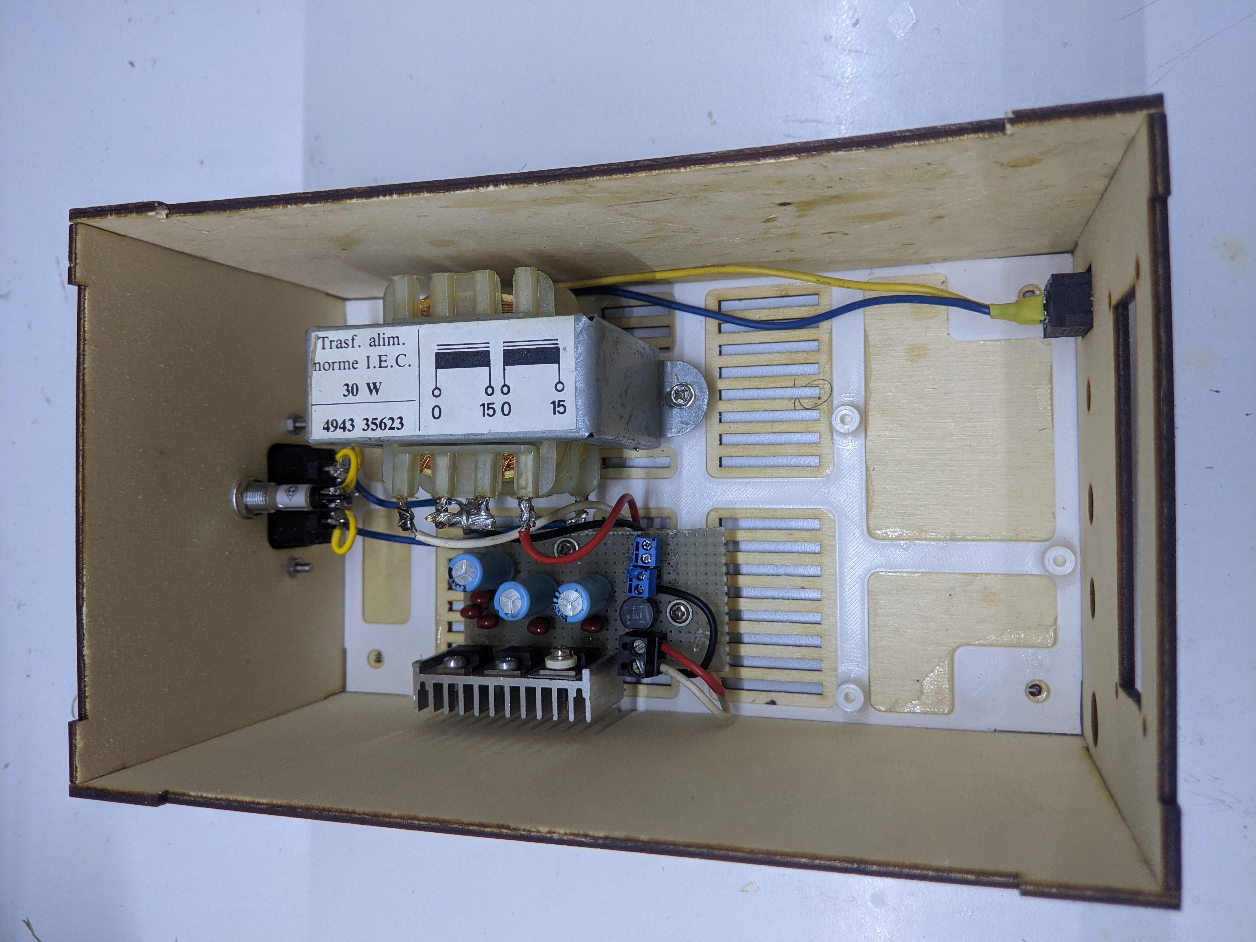
I generated a box with the NiceBox360 plugin. This will be laser cut and there are tabbed cutouts on the walls so they can snap-fit together.
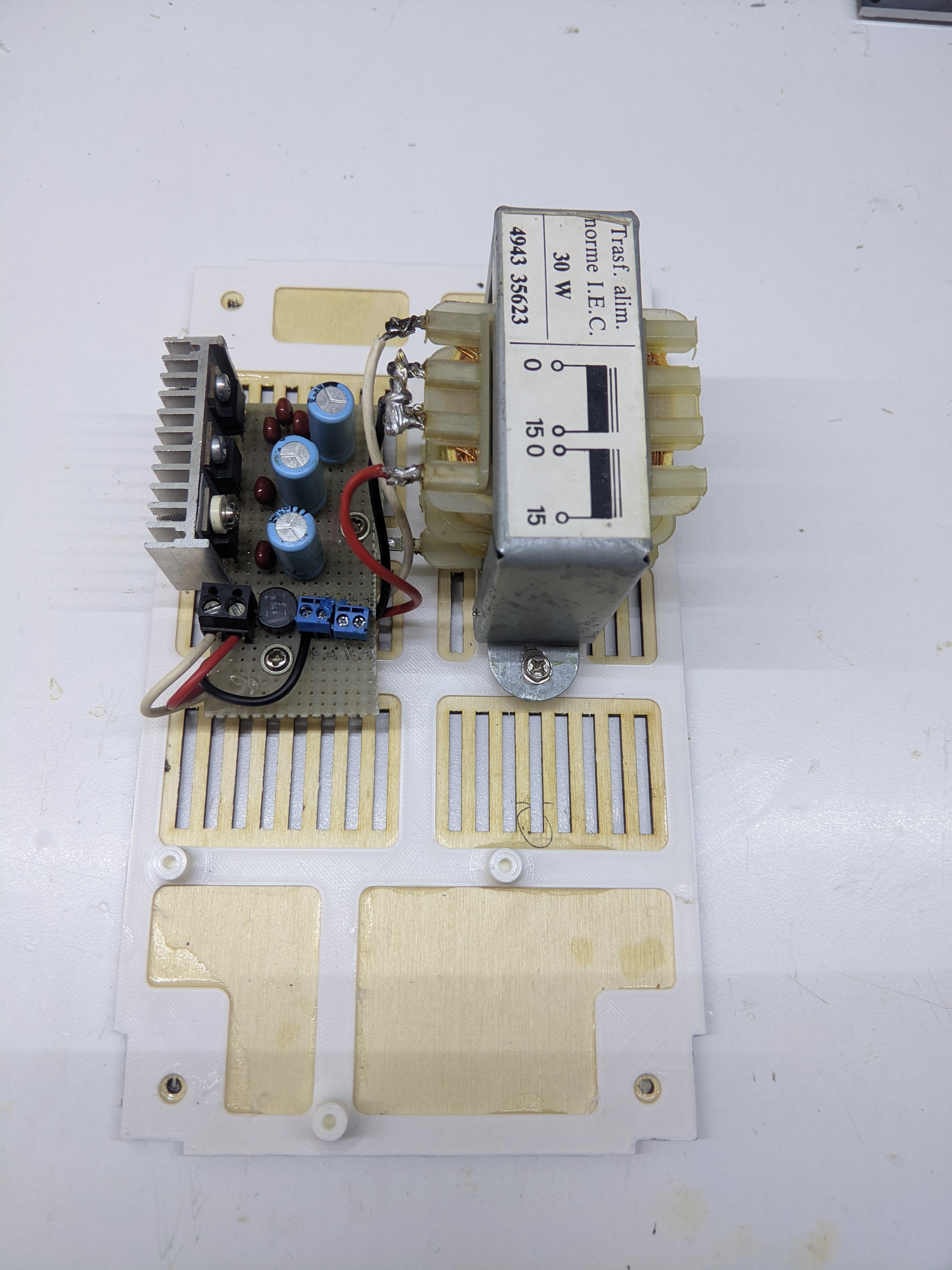
I printed an image of the bottom plate on an A4 sheet of paper. I then placed the components on it and marked where the screw holes would have to go. I mesured them with a caliper and brought those back into Fusion 360.
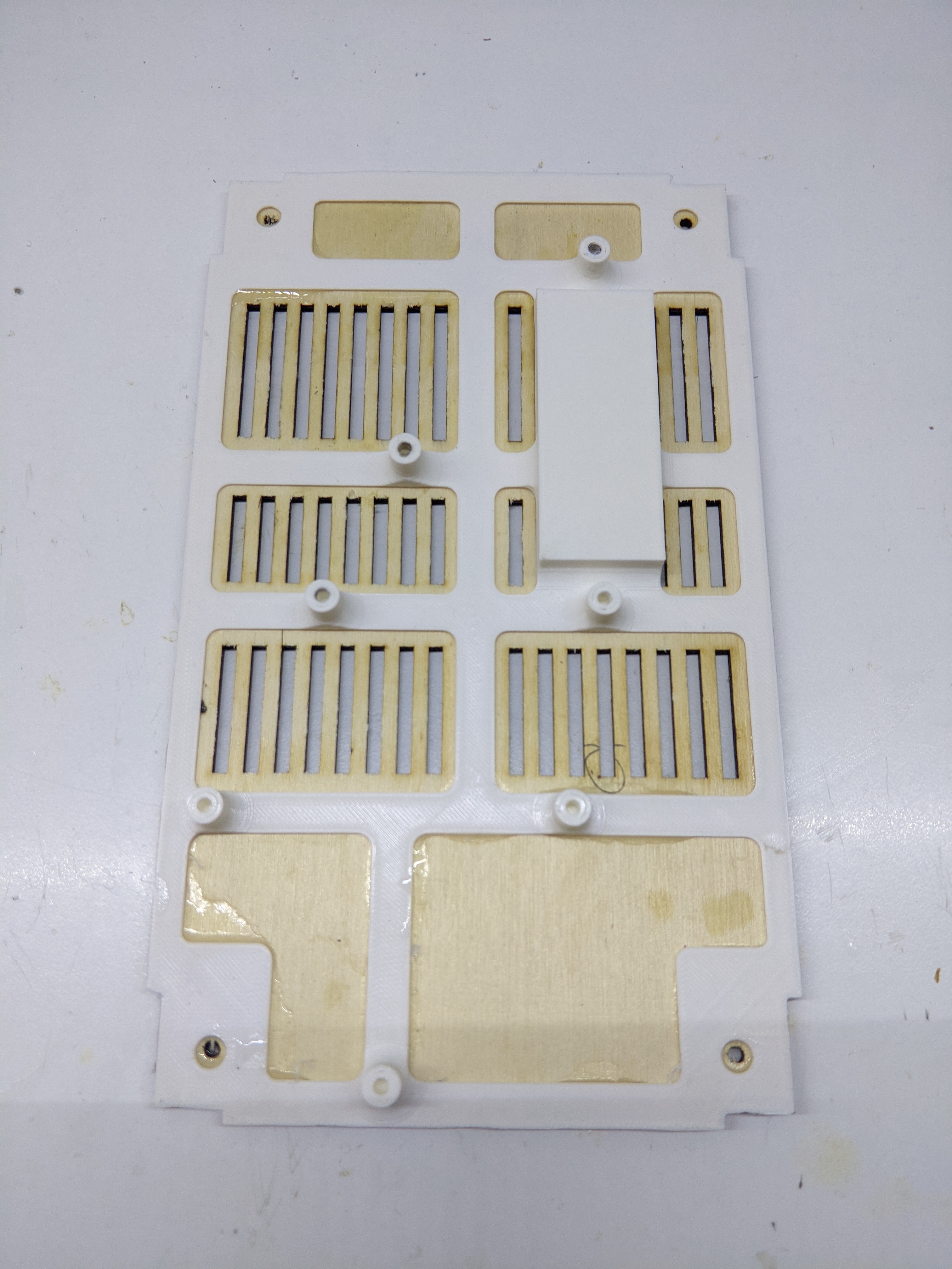
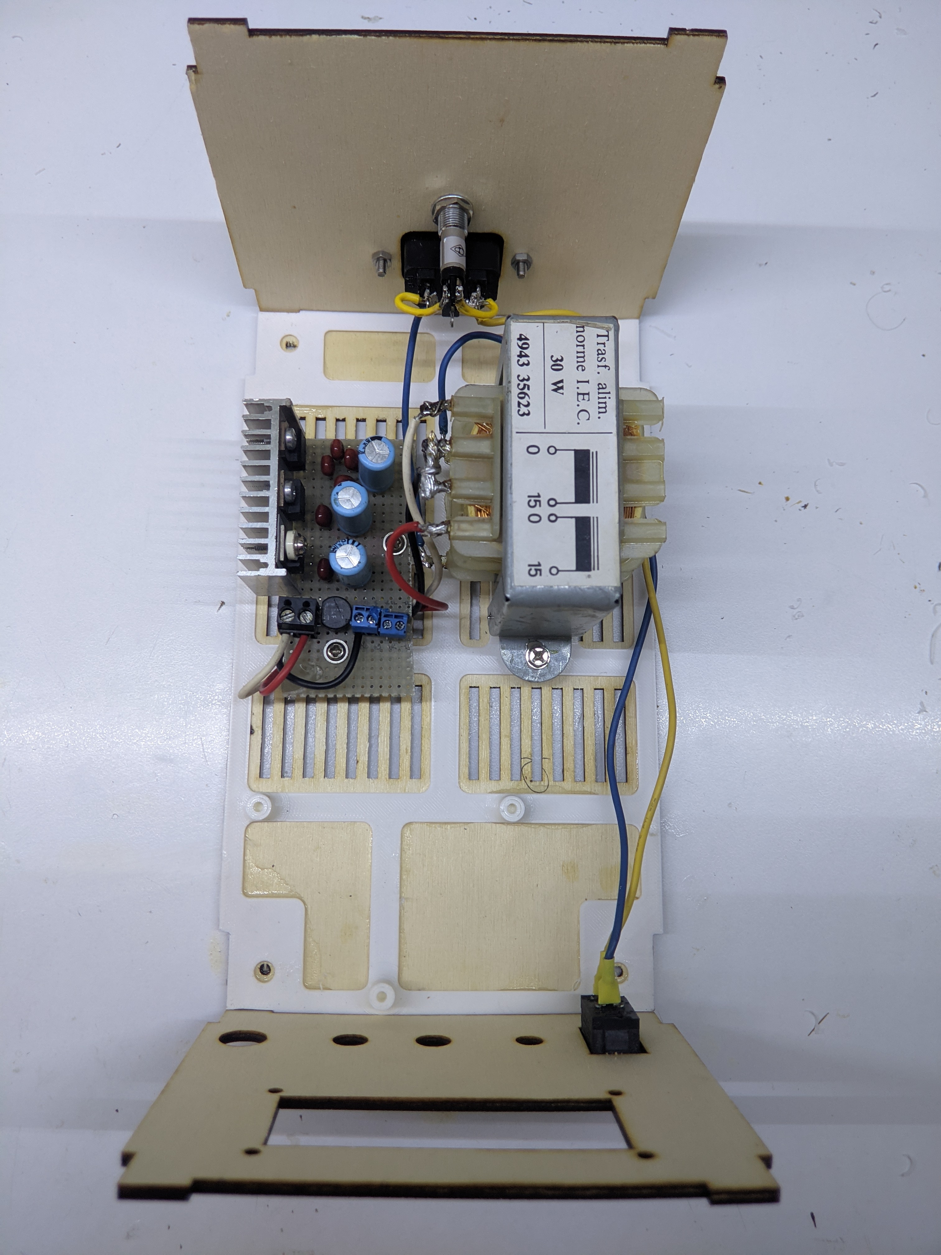
I made a plate to which I will screw the boards and the transformer. It has little columns with screw holes in the places that I marked on the paper. This will be 3D-Printed then glued to the bottom wooden plate. The plate is a little offset from the bottom plate so that wires can pass under it and air be sucked up by the vent.
Finally, I made vent holes on the bottom and on the top, so that the fan (on the top) can draw air from the bottom. I cut mounts for the AC power plug on the back, and holes for the BNC connector, the encoder, the potentiometers and the LCD screen on the front.
