Driving a Apex P241281 Display with Arduino
Together with the SDA5708 Display I also got my hands on some of these LCD. They were dismantled from some old badge-reading terminals that my dad’s workplace was throwing away and my dad brough home.
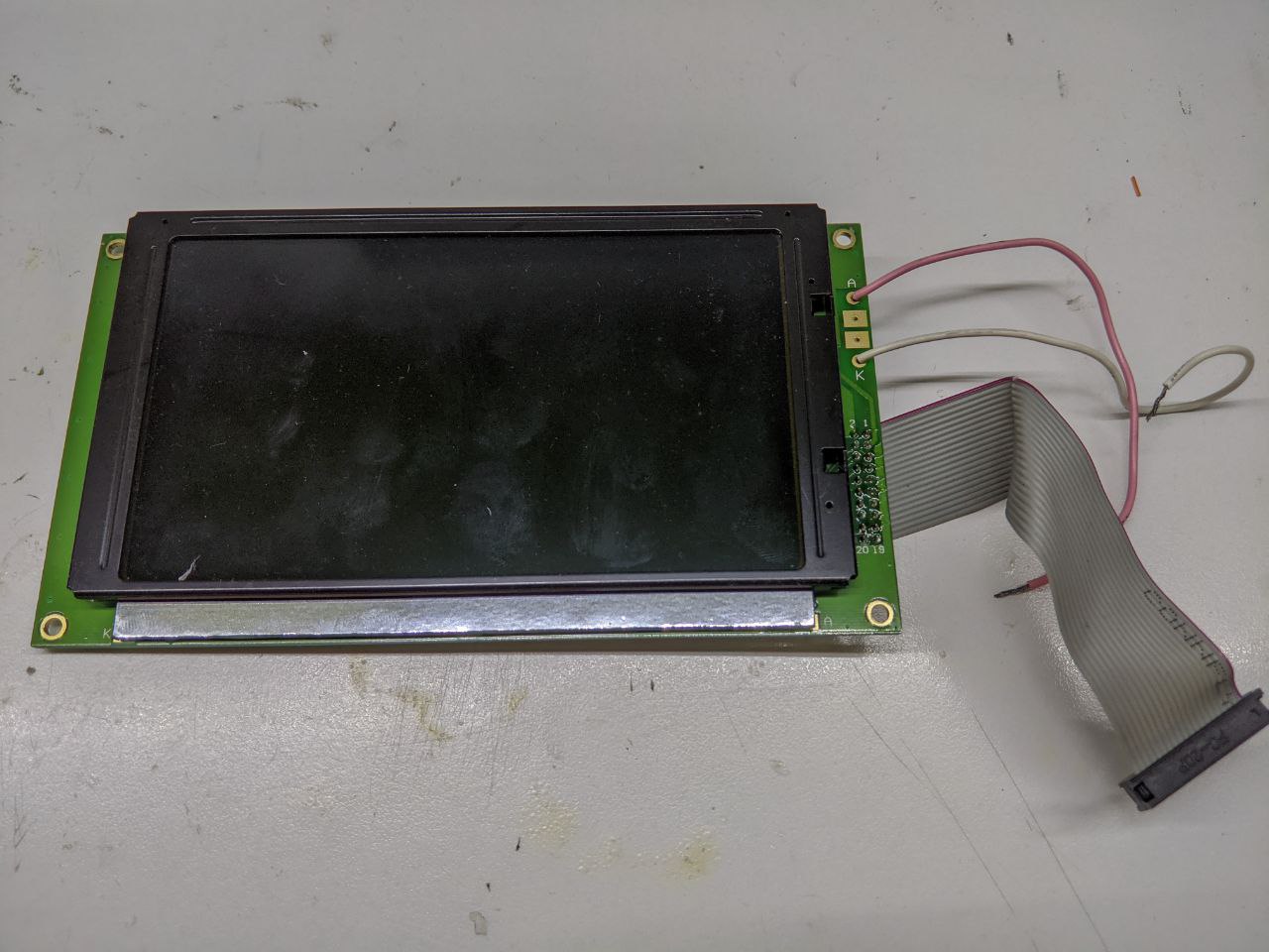
I actually got my hands on two different variants of this display. The one mentioned in the title, the Apex P241281 and a Data Image PG24121A. The display are mostly equal, the only difference being that the former is backlit by a LED and the former by a classic lamp with a boot converter to drive it.
Figuring out the pinout
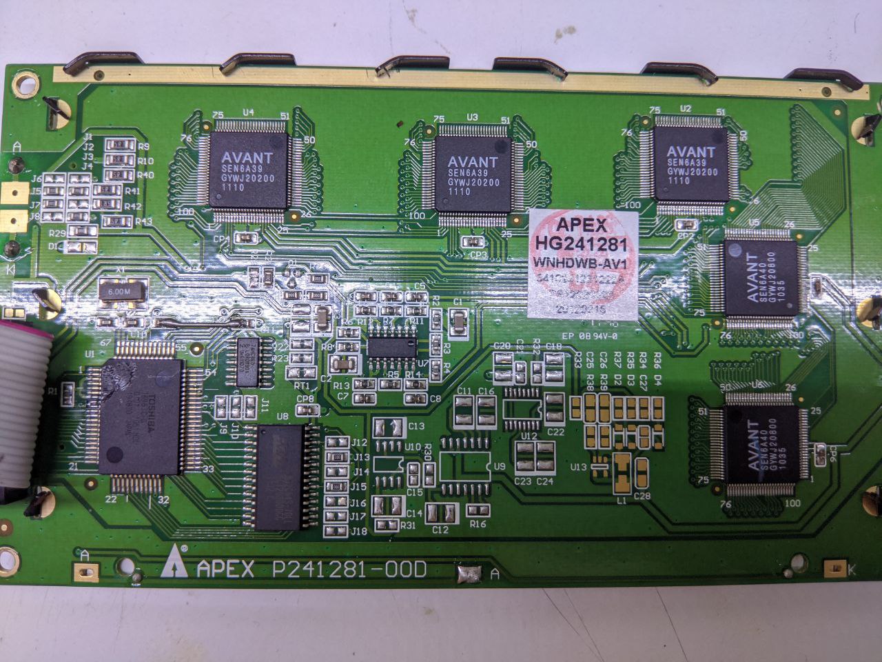
I started by looking up what the ICs on the back on the display were. The star of the show is the big one next to the connector: the Toshiba T6963C is the LCD Controller. This is the datasheet. There’s also this document from SparkFun with suggestions on how to drive it.
It seems I only need to drive the D0 to D7 data pins and some control pins like W/R, CE, C/D and a couple others. From the PCB it’s easy to see that these pins are the only one wired to the connector that goes back to the main PCB, so it’s only a matter of checking which pin of the T6963C ends up on which pin on the connector itself. One end of the connector is soldered on the PCB, so the quickest thing to do was checking which solder point traced back to a pin on the T6963C. However, they are on different sides of the board. This was a two-person job: while I held the board vertical and one probe on a pin of the controller, my dad probed the solder points on the other side of the PCB with the other probe of the multimeter. This is the pinout:
| Connector pin | T6963C pin |
|---|---|
| 1 | PCB “Ground” |
| 2 | Vss (T6963 Ground ) |
| 3 | Vdd |
| 5 | WR |
| 6 | RD |
| 7 | CE |
| 8 | C/D |
| 10 | Reset |
| 11 | D0 |
| 12 | D1 |
| 13 | D2 |
| 14 | D3 |
| 15 | D4 |
| 16 | D5 |
| 17 | D6 |
| 18 | D7 |
As you can see from the table, there seem to be two different Grounds for the same PCB. I couldn’t really figure this one out: the pin I call “PCB Ground” is connected to the metal part of the LCD itself but it not connected to any IC. It’s not even connected to the backlight cathode. I decided to just ignore it and, spoiler alert, the whole thing worked fine without it. I haven’t checked, by I suspect it might have been connected to the Earth of the power supply.
So, anyway, I wired up the display to an Arduino Mega (which was the one of the three microcontrollers with 5V logic I had laying around: that and two Uno’s) using dupont connectors. It was messy to say the least.
I also found out that this controller is supported by the U8GLib library, so I didn’t need to write another library myself.
Driving the display
It was simply a matter of using an example script from U8GLib, and wiring the Arduino according to the code.
U8GLib examples are made for a variety of display controllers, and different variants of the controller themselves, all you need to do is uncomment the line for your specific one. The T6963C comes in different resolutions: 240x128, 240x64, 128x128, 128x64. The resolution and font size are set by pulling some pins high or low. This is from the datasheet:

This is how the pins are on my PCB:
| Pin | State | Meaning |
|---|---|---|
| FS0 | Low | ↓ |
| FS1 | High | Font 6x8 |
| Dual | High | Only one screen |
| MDS | High | ↓ |
| MD0 | Low | ↓ |
| MD1 | Low | 16 lines, 128 rows |
| MD2 | Low | ↓ |
| MD3 | High | 40 columns |
Pull all of this information together and you get that this display has a resolution of 248x128, using a 6x8 pixels font. So I uncommented the corresponding line in the U8GLib example, which was:
U8GLIB_T6963_240X128 u8g(8, 9, 10, 11, 4, 5, 6, 7, 14, 15, 17, 18, 16); // 8Bit Com: D0..D7: 8,9,10,11,4,5,6,7, cs=14, a0=15, wr=17, rd=18, reset=16
I honestly found the comments on the line a bit confusing: what is CS? A0? I haven’t got those on my controller!
This post on the arduino forum helped me understand better. I guess CS would stand for Chip Select, while CE stands for Chip Enable. Different name, they mean the same thing in this case: while Chip Select/Enable is pulled low, the controller listens for commands from the CPU (in this case, the microcontroller). I can’t phantom a working acronym that would link A0 and C/D honestly, though.
The parameters are then be as follows:
U8GLIB_T6963_240X128 u8g(D0, D1, D2, D3, D4, D5, D6, D7, CE, C/D, WR, RD, RESET)
It never works the first try, does it?
Well, nothing blew up, the wiring seemed correct, yet no image would appear on the display whatsoever. At first I though something was wrong in the wiring, maybe a wire not working or an interrupted trace in the connector cable, but checking with the oscilloscope everything looked right and there were no missing signals.
I read again that post and I noticed OP’s display also had a contrast control pin. Now, this seems like a good explanation to my problem: too low of a contrast and there is no image! There is not contrast control on the T6963C, which means it must be somewhere else.
I took one of the machines the display was originally connected to, turned it on, and started probing the pins of the connector, without having the display actually connected. I noticed two pins that were missing from my pinout: pin 4, sitting at about -12V, and pin 19 sitting at 5V. One of them could be controlling the contrast. I used an old ATX PC Power supply to get -12V (it is actually the same I used for the initial tests of my function generator - I really should make a prober lab bench power supply out of it).
Lo and behold, the moment I connect -12V to the display, the Hello World text appears on the display.
Pin 4 does infact control the contrast. The more negative it goes, the more contrast. The contents of the display start being visible going a bit lower that -11V, and the image is clear to watch at about -12.5V.
Pin 19 didn’t seem to have any visibile effect on the display, and it isn’t actually connected to any pin on the controller itself, not even Vdd.

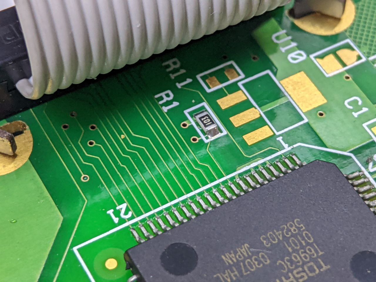
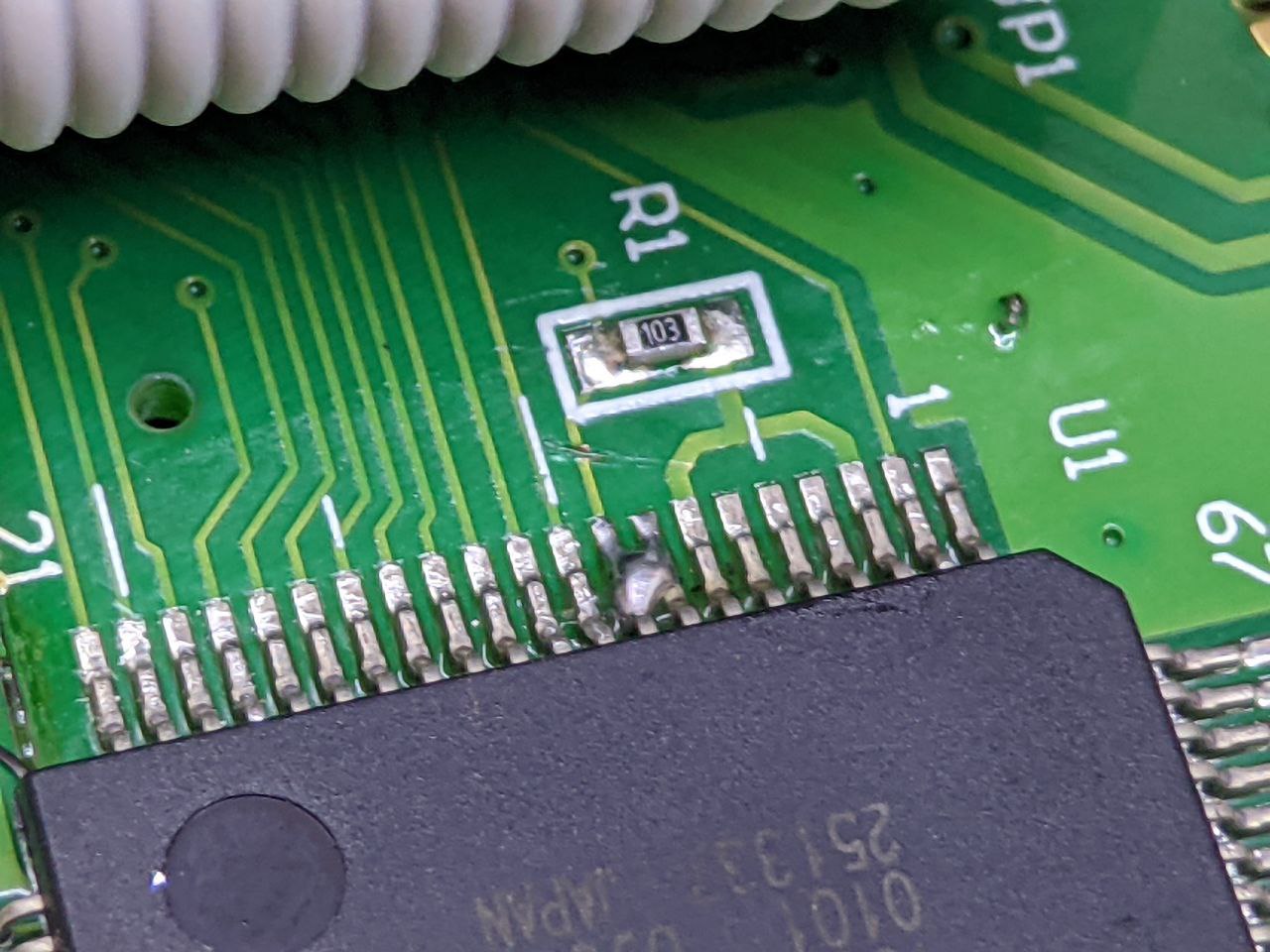
As you can see, though, the image is pretty messed up. This is because U8GLib renders 8x8 pixel fonts, and my display is set to use 6x8 fonts. To fix this I need to pull FS1 low, since FS0 already is. I did this by cutting the trace that pulled FS1 high at bridging the FS1 and FS0 pin together on the T6963C, since FS0 was already wired to ground. Here’s the before and after:
At this point the image would show up just fine. It is rotated, but that can be changed in software.

Making it nice
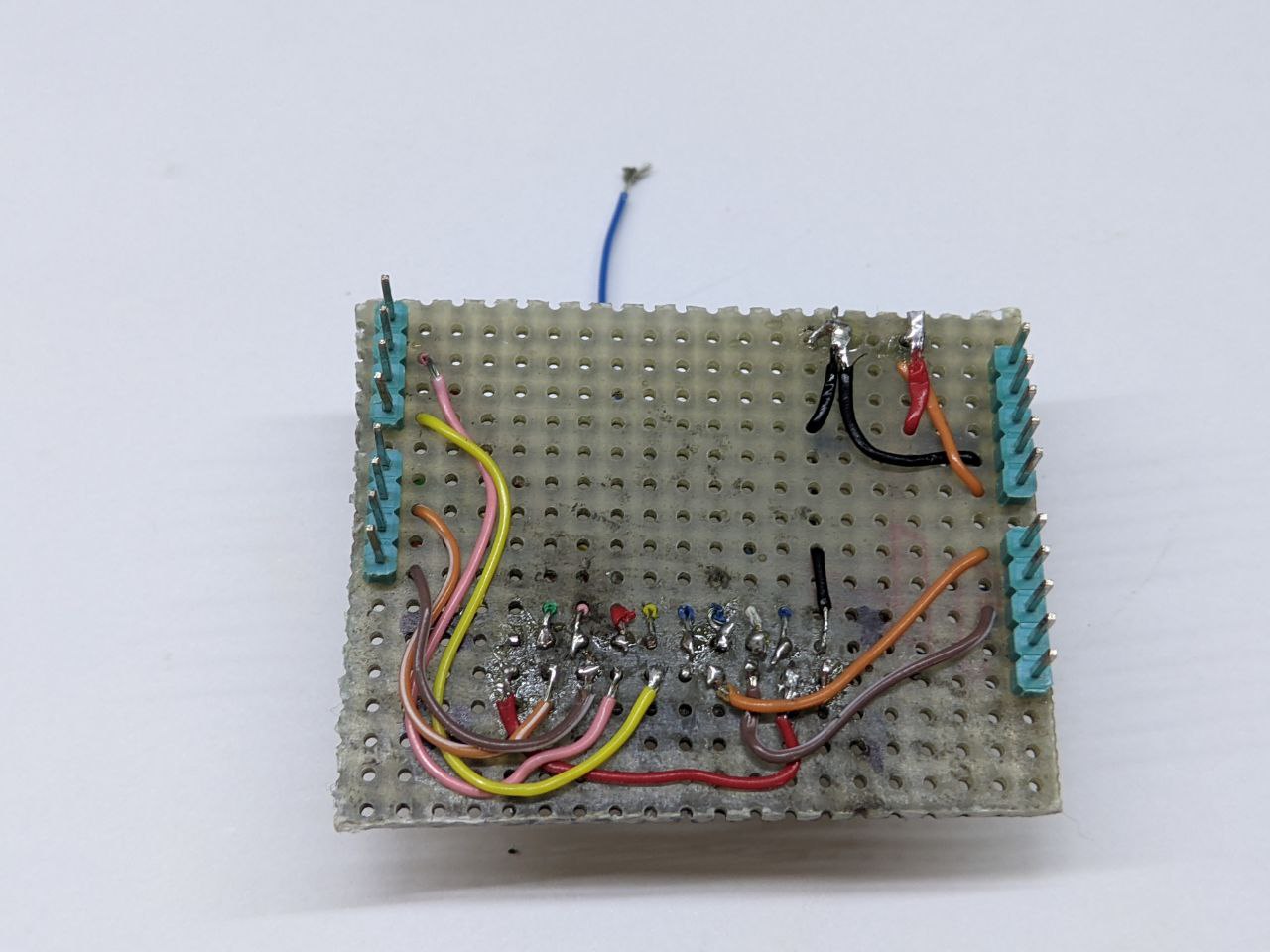
Having like fifteen dupont connectors going from the LCD to the arduino is really an atrocious way of wiring the two together. I decided to solder the connectors to a little piece of stripboard and build a sort of shield that would sit on the arduino, exposing a connector to easily plug and play different displays.
Here it is, alone and on top of the Arduino Mega. I only had a 1-sided stripboard, so I had to make do with some strange soldering. It is hard to catch on camera, but there is some space between the stripboard and the display header. In that space I could solder the header to the stripboard. I only did it on the four corners, though.
I tried to have the components placed in a sensible way, but I somehow ended up the the mirrored version of the optimal placement, so there’s a lot of wires crossing.
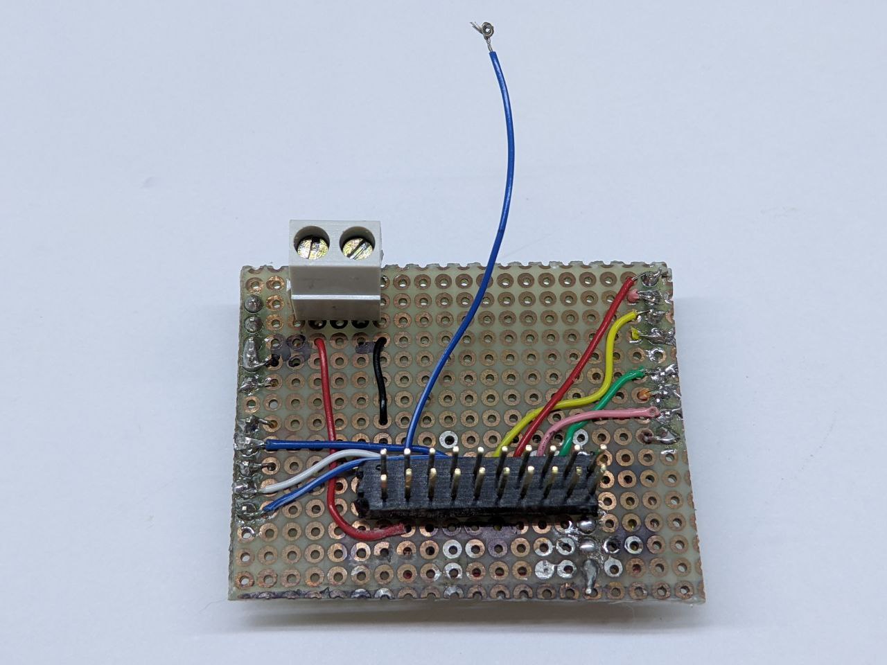
The blue wire is the contrast control pin, which is directly connect to -12V on the PSU. I found that -12V was a good voltage to set the contrast to.
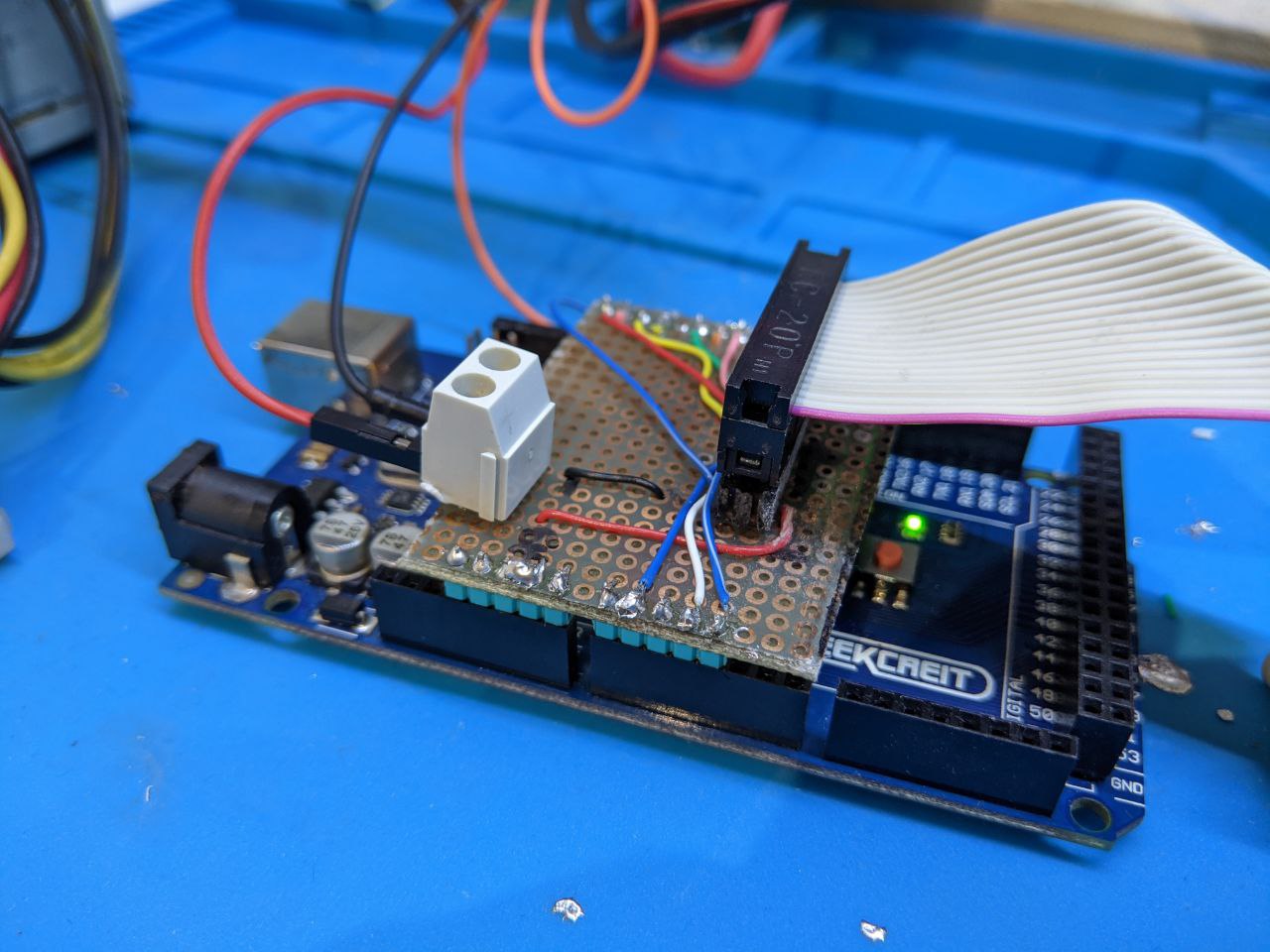
Here is a photo of it all together

Maybe in the future I’ll make a prober PCB for this shield, including a trimmer for contrast control.
Cheers! :)