On the RomeCup 2024
It’s the time of the year again for the RomeCup! The RomeCup is a yearly event held by Fondazione Mondo Digitale in Rome, Italy, revolving around robotics and artificial intelligence. For three days, from Wednesday to Friday, the RomeCup features talks, events and robotics competitions. Every year it is held in a different location, with the finals of the competitions always taking place in the Capitol. Needless to say that my absolutely favourite part are the robotics competitions! Back when I was in middle school I used to participate in the Rescue Line category, and I even scored a second place at my second attempt, when I was thirteen. When I was in High School, and was part of the SPQR Robotics Team we participated in RomeCup each year, and we got first both times, qualifying for the worldwide tournament.
Now that I’m out of high school and in university I can no longer take part in the competitions and I miss it greatly, but they’re aimed at school students after all and we ought to have younger students have a go too. But for a couple of years now I have been working for Fondazione Mondo Digitale: I hold courses and workshops about coding and robotics for school students, help mantain the internal FabLab active and help organize events. Which means I also help making the RomeCup come together. Being on the organization side really makes you appreciate all the work that goes into making such an event work, which you often don’t mind when you’re competing and going mad because your robot is acting up.
My dear friend and ex-spqr-teammate Davide Belli also works for Fondazione, and our job this year (and last year, actually) was to take care of the Soccer league: mainly we had to overhaul the playing fields, but we also got to be referees for all the matches. Our other job, at the FabLab, with the wise direction and precious help of our friend Daniele Vigo (which is responsible for everything FabLab) was also to overhaul the playing fields of other categories: the Rescue Line and the Explorer.
I’d like to write about how we rebuilt the playfields for all the categories in the competition, what our objectives where, the design choices and a retrospect on their effectiveness. Most of my work went into the Explorer playfield, so I will focus on that in this post.
Soccer
Actually, we rebuilt this one last year. The previous fields where the same me and Davide played on in 2019 and 2022 respectively and they where absolutely terribile. Now, to resemble a human soccer field, the RoboCup Junior one is built on top of a green moquette. The rules give only one constraint on the moquette: it must be green, preferably a darker tone. This means that for each competition you attend, you can (and most surely will) find a field with different texture, color tone, depth, grip and other general characteristics to the one you are used to. The old moquette used to separate in long strands of cloth when they were slightly pulled by the robots’ wheels. Those strands got into the shafts of the motors and the wheels, blocking them and preventing them from turning correctly. Basically, it was a great recipe for breaking motors and robots.
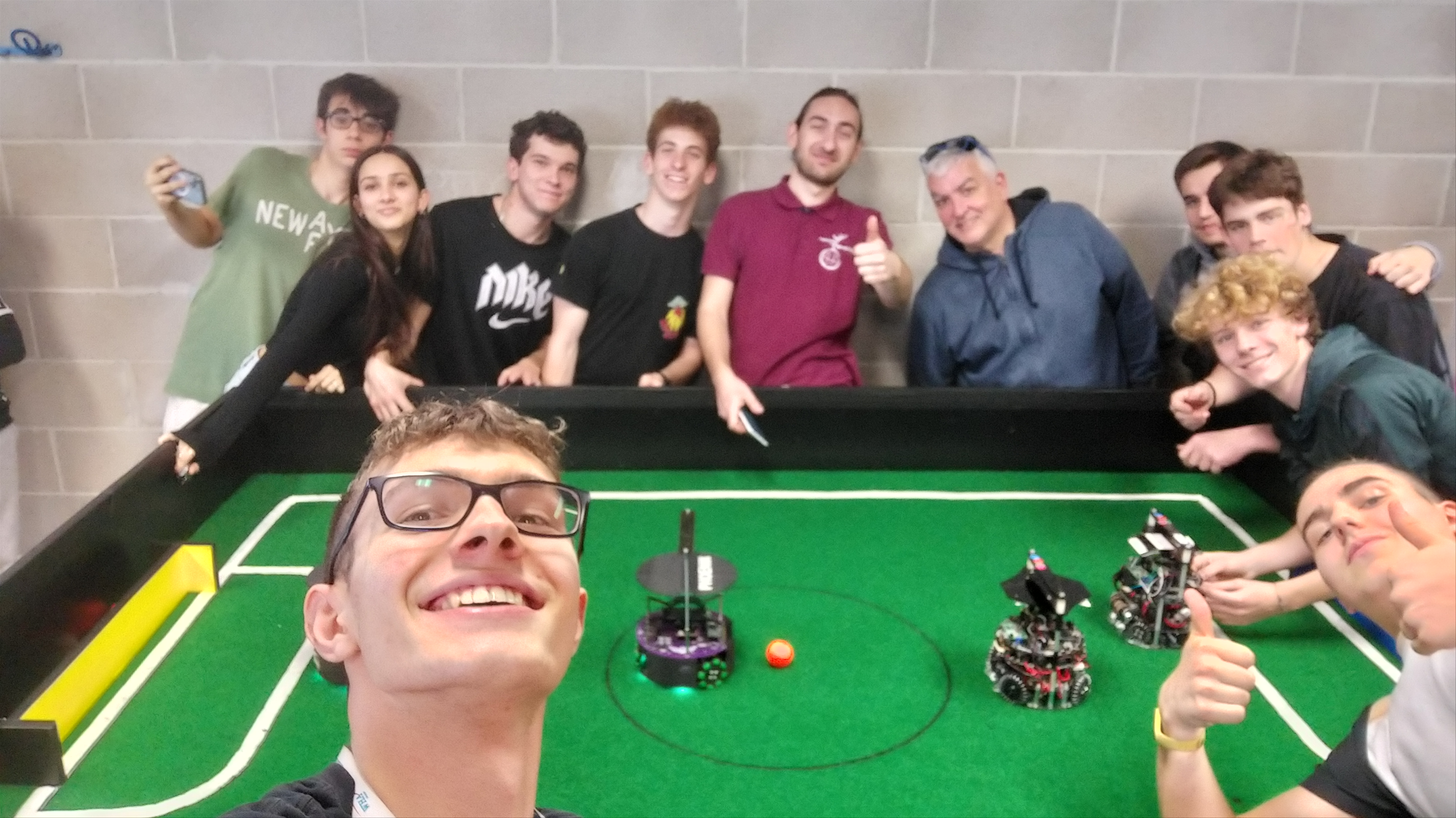
Being on the organizational side this time, we pushed for changing the moquette, taking on the occasion that the rules had changed enough that a new field was in need. After about four weekends of hard work, we had rebuilt almost from scratch not one but two playing fields, with a moquette very similar that was used in both the Syndey 2019 and Bangkok 2022 worldwide tournaments. We had a sample back at school, at ITIS G. Galilei, has we had rebuilt the field at school right after the Sydney 2019 worldwide tournament and we had taken a sample of the moquette. Our hard work payed back, the fields really were amazing. Unfortunately a lot of competitors build their robots with the chassis way too low and most of them had problems with the chassis grinding on the moquette.
With the hard work done last year, this year we just had to make the lateral walls a bit higher to have them abide to the rules, which was something we had overlooked last year. Plus giving a new hand of colour to the goalposts and fixing the white tape we use for the out of bounds lines.

Explorer
The Explorer category is exclusive to the RomeCup. In this category, robots built and programmed by high school students have to navigate through a maze looking for “hotspots”. There are three types of hotspots, each earning a different amount of points.
- Gas sources (1 point)
- Light sources (2 points)
- Sound sources (3 points)
The playing field is 4x2 meters black board, which we made out of wood, and the hotspots (or stations) are wooden boxes measuring 33x40x22 centimeters.
State of the art
Up until a couple of months ago, the playing field was divided into 4 1x2 meters thick chipboard panels. The assembly process went like this:
- Lay down the panels in the correct order on the floor, with the upper side facing the floor (thus working on the back side)
- Run the cables with the banana plugs into the pre-cut holes in the panels and down to one side, which will be were the power supply and signal generator will go
- Screw the panels together, using 8mm bolts and nuts that go through the wood stand off glued to the back of the panel
- Flip all the panels, now screwed together, to have the up side face up.
Notice a bit of a problem with this? There are a few:
Precut holes in the panels mean that only a certain number of configurations for the maze are possible. I won’t bother counting them, but they are not a lot. At most you can change the type of hotspot in any given position
You have to pre-route the cables. This means that when you flip all the panels you have to pay attention not to squish them and break them.
Once the panels are flipped it’s good to check that the cables are not broken. For this I just used a multimeter in continuity mode. Unfortunately, the cables need to be very long and do not have much wiggle room once they are in place, which means you better have long arms and long probes for your multimeter.
You actually have to flip the panels. We are talking 4 1x2 meters 5cm thick (+ 5cm standoff) now all screwed together, as there is now way to screw the panels once they are the right side up. Those are heavy. Like, incredibly heavy. We are talking a -at least- 6 people job heavy, and it obviously must not break because of poor coordination between all the people.
Bonus: the playing field was quite old and the wood was starting to crumble after years and years of screwing and unscrewing and transporting and general abuse by students.
Making it better
So our goal in remaking the field was to make it as easy and quick as possible to be transported and assembled. First of all, we wanted to place the panels on the floor right side up from the get-go. Having to route cables on the back side and then flip the panels is just a bad idea. This meant that the routing had to be already done before placing the panel on the floor. From this naturally came the second need, which was to have each hotspot station independent of the others, and the only eletrical signal running in the cables beneath the panels had to be power.
Mechanics
To tackle the first problem we decided to have smaller panels of less thick chipboard. We then drilled 9 holes into them, in a 3x3 grid. In each hole we placed a female connector, barrel jack on one side, sitting flush with the upper side of the panel, and terminal block on the other side, which would be the under side of the panel. Each of the connectors were wired in parallel. The use of terminal blocks meant that we only had to use a screwdriver to make connections, never a single solder joint, which in turn meant that we were saving the time needed for soldering and that the connections were easier to repair when on-site at the competitions, should some wires come loose in transport (fortunately, this has yet to happen).
Each panel has an outgoing male barrel jack connector and an incoming female barrel jack connector, which allows for inter-panel connection while still mantaining all the panels connected in parallel (eletrically speaking).
Other, smaller, holes on the border of each panel were drilled to use extruded alluminum profiles to mechanically connect panels to each other, and stratified polyamide panels were cut to fit inside the aluminum profile groves to make the external walls of the maze.
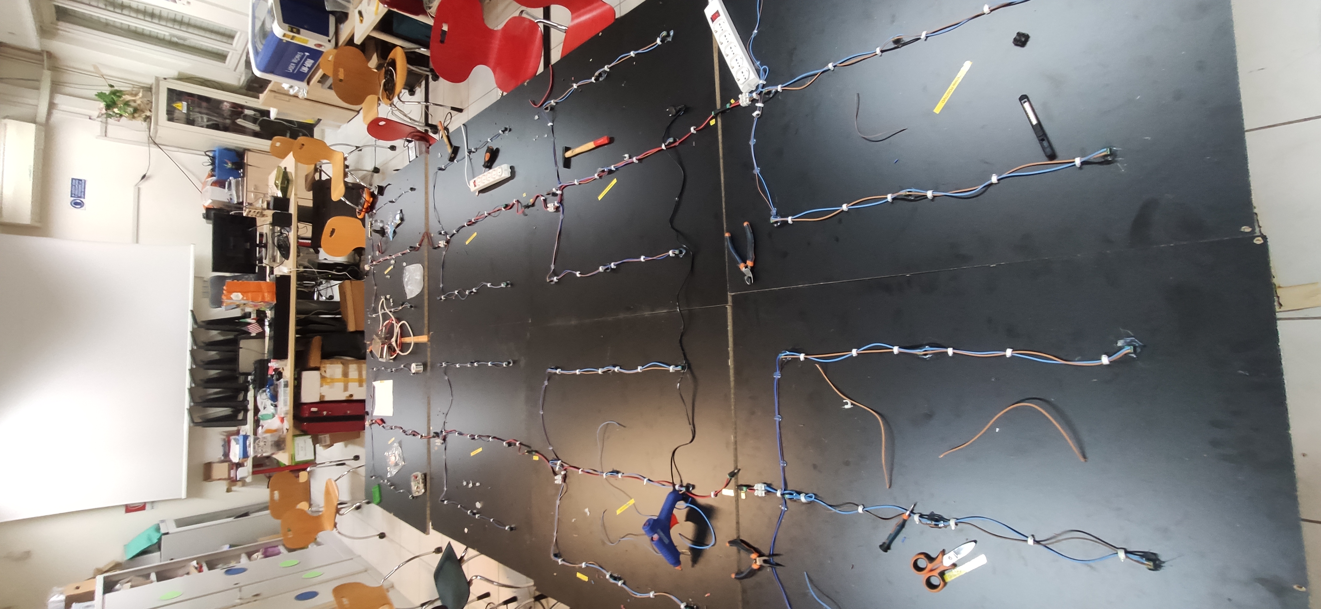
Here’s what the underside of the field looks like, with the cables running through. Needless to say it took the majority of the space at the fablab. We didn’t have a banana quickly available, so we used Daniele for scale.

Now to the hotspot stations. To have them indepedent from each other, we decided to have each station have its own standalone PCB, which would only take in the power coming from the barrel jack connectors and use it to do whatever is needed. This also means that if we wanted, in the future, to add new types of hotspots, we’d only have to design the PCBs for the job and stuff them inside a station.
Electronics and custom PCBs
Anyway, currently there are three types of hotspots. The gas source is simulated by using alcohol fumes. We use common denatured alcohol, which tends to evaporate at ambient temperature. Davide 3d-printed a holder for the alcohol with holes on the top, to be placed on the playing field. The holder was modeled to stay under 1cm in height, which by the rules is the height limit of an obstacle.
For the light and sound sources I made custom PCBs. The light source PCB is quite boring, just a LED and a 100 Ohm, ½ W resistor, the only notable thing is that I predisposed it with both SMD pads and PTH holes, to have the liberty of using any component I was able to find at the cheapest price, and not lock myself into using expensive or hard to source components.
Now, the sound boards are quite interesting and I take a bit of pride in them. I really really like how they turned out, and they (almost) worked at the first try! Before embarking on this journey, I talked with an old teacher of mine back from SPQR, a RoboCup veteran, which also has some teams competing in the explorer category and had a hand in writing the rules for the explorer. The sound the robots have to recognize is a square wave centered at 4kHz. I initially tought to just use a NE555 oscillator, but turns out that not only my teacher preferred to have a sine wave for the robots, it also needs to be extremely precise in frequency, and a NE555 just isn’t cut for the job. And here I enter the stage: as for my high school diploma project I built a DDS signal generator, and I know for a fact that those are incredibly stable in frequency, down the fraction of a Hertz.
So it was just a matter of choosing the right microcontroller with an integrated DAC, and possibly and integrated voltage regulator because that doesn’t hurt. My eyes fell on the Seeedstudio Xiao SAMD21, but it seemed way too overkill for the job. And the price was going to be a problem since I was planning on making at least 10 of these boards and wanted to keep it simple and cheap.
Then the realization
At this point I started looking for cheaper microcontrollers. After a bit of research, I started looking into the AtTiny family of AVR microcontrollers. At just about 0.5€/piece on DigiKey, I could get my hands on some really nice AtTiny412’s: up to 20Mhz clock, integrated oscillator, integrated 8bit DAC, with arduino framework support using the amazing megaTinyCore. Having only 256B of RAM and 4KB of flash was going to be a problem, but after all my code was going to be really simple, but the integrated oscillator meant I could just plop them on a PCB and give them power to work, no need for an external quartz oscillator, which in turn brings down the cost by about 2€ per board.
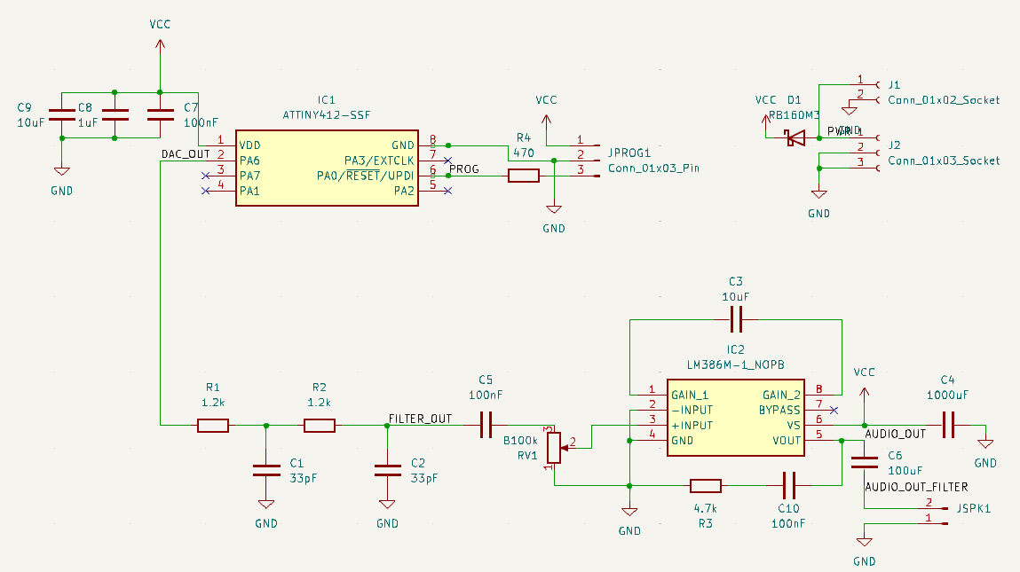
After some experiments using other microcontrollers and a LM386 audio amplifier, I started designing the PCBs around the AtTiny412 and the LM386 amplifier, using all SMD components so that I could have the PCBs assembled my JLCPCB upon ordering and save a lot of my own time, since I was in a hurry at this point. The PCBs are quite simply and feature the microcontroller, a filter stage using a double RC cell (with the cutoff frequency set at just over 4kHz using 2 1.2kOhm resistors and 2 33nF) capacitors and an audio amplifier stage to drive the speaker.
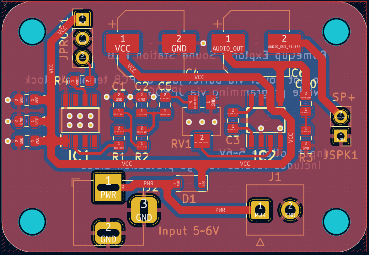
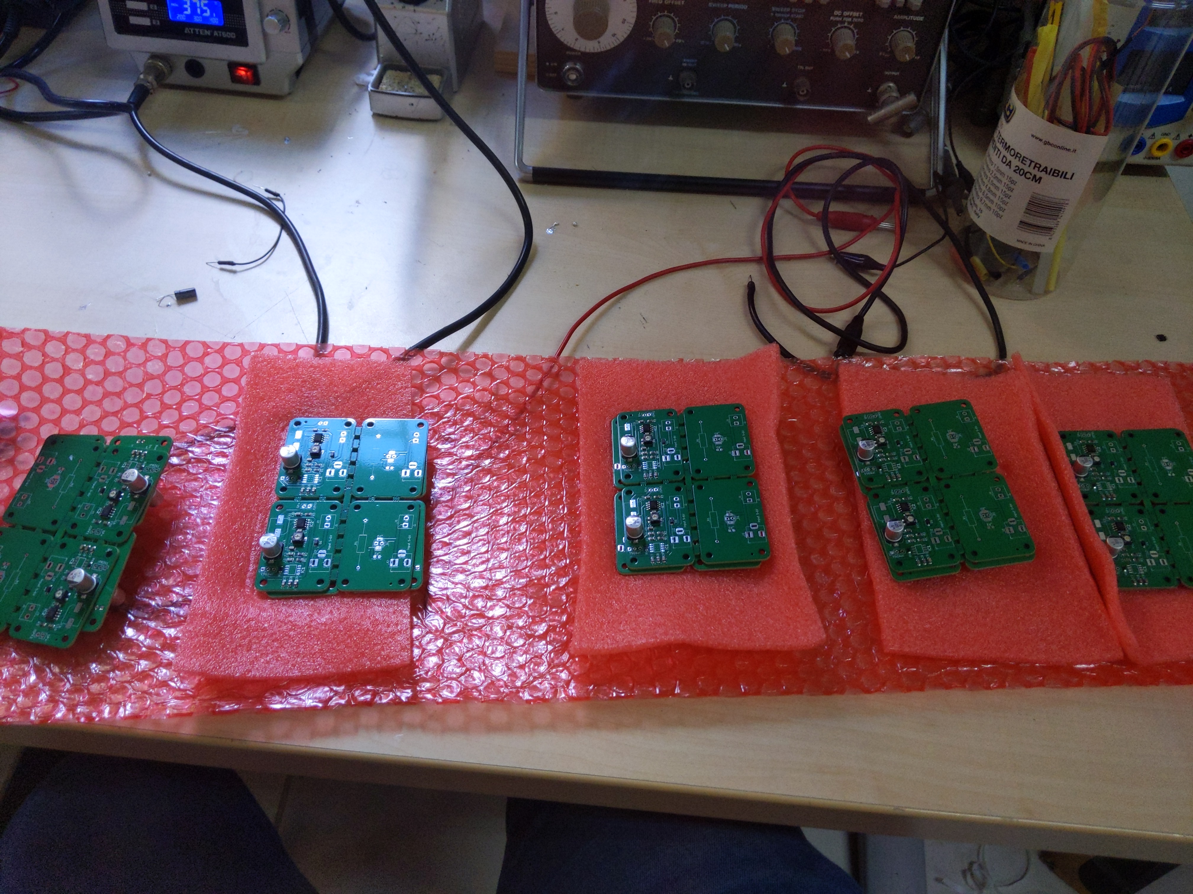
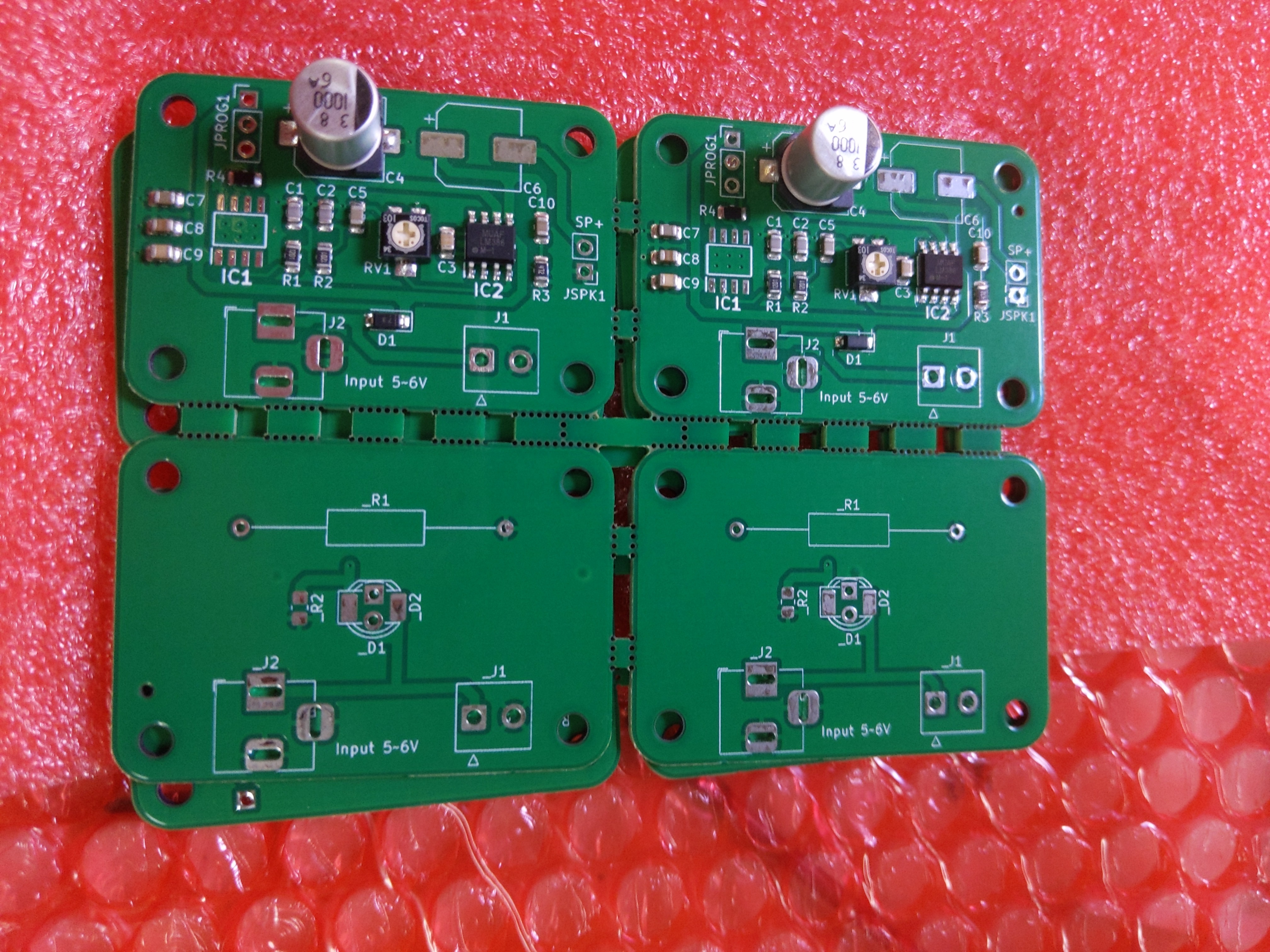
Here is how the final PCBs arrived, leveraging JLCPCB incredibly cheap prices, I made panels to have more boards in the same space and keep tons of spares.
Problems problems problems
To generate the sine wave with the DAC I used the same DDS technique with a phase
accumulator which I used for my function
generator: I generate a lookup table with discrete samples of the sine wave, and then
calculate a coefficient, delta_phi, which tells how much further in the lookup table I must
go at each cycle. From here I start a loop, in which delta_phi is summed to a phase (the
phase accumulator) variable each cycle, whose integer part
represents the index in the lookup table. By varying delta_phi based on the sampling
frequency (how many generation cycles in a second), the lookup table size and the requested
frequency for the output waveform. This whole routine acts like a phase-to-voltage converter
using the values stored at each index of the lookup table.
Once I had uploaded the code the the AtTiny412, mostly a copy of the code I used on the Teensy 3.5, I started testing the boards. On my test circuit, even when using an AtTiny soldered on perfboard in a frankly barbaric way, I could get a nice 4kHz sine wave, stable in frequency which also sounded good on the speaker, if with a bit of noise. However, on the PCBs I had just got, I could hear a lot of noise as a background to the sine wave. Actually, the sine wave itself seemed to be all but stable in frequency judging by ears.
This was clearly not related to the fact that I mistakenly ordered my PCBs with 33pF capacitors instead of 33nF ones, thus having the cutoff frequency at 4MHz instead of 4kHz, which had me order 33nF capacitors in a hurry on TME, which luckily has a 1-day shipping plan, because at this point I had already changed all 40 of them by hand and yet the problem was still there. After a lot of experiments, I came to the conclusion that it was also not related to any other error in any point of the circuit. In fact, if I bypassed the AtTiny412 on the PCB and generated the sine wave with a Teensy 3.5 instead, I wasn’t getting any noise.
At this point my theory was that the DAC onboard the AtTiny had such slower rise times compared to the one onboard the teensy (possibly also related to the much lower clock frequency, almost 10x) that the higher-order armonics generated by the quantized change in voltage were still in the audible range. In fact, the second order RC filter I designed still let through a bit of signals up to 20kHz, which is in the audible range, and judging by ear the noise really seemed in high frequency. At first, and actually until after the first day of competitions was over I just thought I should have designed a better filter.
Solutions solutions solutions
Speaking again
with my teacher, bless his soul, he made me realize that I was doing all my phase
accumulator calculations in floating point, which tends to be quite slow on 8bit
microcontrollers, and, if I may add, having an if statement handle the wrap around inside the generation cycle really
wasn’t helping. This was something that was already on my mind, but I didn’t think it was having have such a
huge impact. So, since the first day of Soccer competitions was only planned for the
teams to settle in and make tests and adjustments, I used a moment of relax (those are rare during
the RomeCup) to read this article by Freescale/NXP, which explained exactly what I needed to do.
Basically, it explained how to perform DDS phase accumulator calculations only using
integers instead of floating points. The idea behind it is that the delta_phi quantity is
bound to be fractional, but it can be expressed as an integer and a decimal part.
Using a 2-byte quantity, we can express the integer part in the upper byte, and the decimal
part, multiplied by 256 (so that it is modulo’d into a byte) into the lower byte. At this point
we have an integer representation of delta_phi which we can sum to an integer phase every
cycle. The current sample to be output on DAC is stored into the integer part of phase, which
can be retrieved by shifting 8 bytes to the right and masking by the size of the LUT. For this
reason, the LUT size is better set to a power of 2. After a bit of fiddling around I set the
LUT to be 32 samples, so the mask is in first 5 bytes, or 0x1F. Doing all the calculations
in unsigned integers has the advantage of automatically taking care of wrapping back to zero
when the integer overflows, thus not needing a dedicated if statement, which can mess up the
sample frequency and generate frequency instability and noise.
However, this method has the drawback of presenting a bit of granularity in the
frequency resolution of the output waveform, given by the fact that we are shriking a 32bit
float into a 16bit quantity and only using 8 bits for the decimal part. This meant that not
all my AtTiny’s could be set exactly to 4kHz, has they present a large variation in the clock
frequency from part to part (the megaTinyCore wiki says it’s up to 10% of the nominal
frequency). There’s a tuning process for fixing this that I really could not get to
work, so my solution was just to use a bigger integer. Using a unsigned 32-bit integer I could
dedicate 1 byte to the integer part of delta_phi and the rest to the decimal part,
multiplied by 2^24. Having a 1-byte integer part is a direct consequence of having only
256B of RAM on the uC. Proceding by powers of two, 128 is the last quantity I can use that
can be contained in 256B of RAM. Initially I had the LUT size set to 128 to buy myself a bit
of frequency resolution, only with later experiments I discovered that setting the
LUT size to 32 was fine when using a 3-byte digital part. Coincidentally, this is the same exact number of bits used for
the mantissa and one bit more used for the exponent of a 32-bit float as estabilished by IEEE 754.
Using more bytes gave me the resolution I needed, and I was able to calibrate all 6 boards on the field, plus a couple of spares I was keeping for experiments myself, to exactly 4kHz.
The morning after, I spent about 10 minutes manually going through all the sound station on the play field and recalibrating them, accurately checking the frequency on the oscilloscope. The difference this made was immediately noticeable: all the noise was gone. Let me tell you, a 4kHz sine wave is quite an acute and annoying sound to hear, but at this point I could recognize it by ear and those sure were 4kHz!
You can try for yourself. I uploaded all the project files: KiCad boards, manufacturing files, code for the AtTiny and BOM to a git repo(mirror)
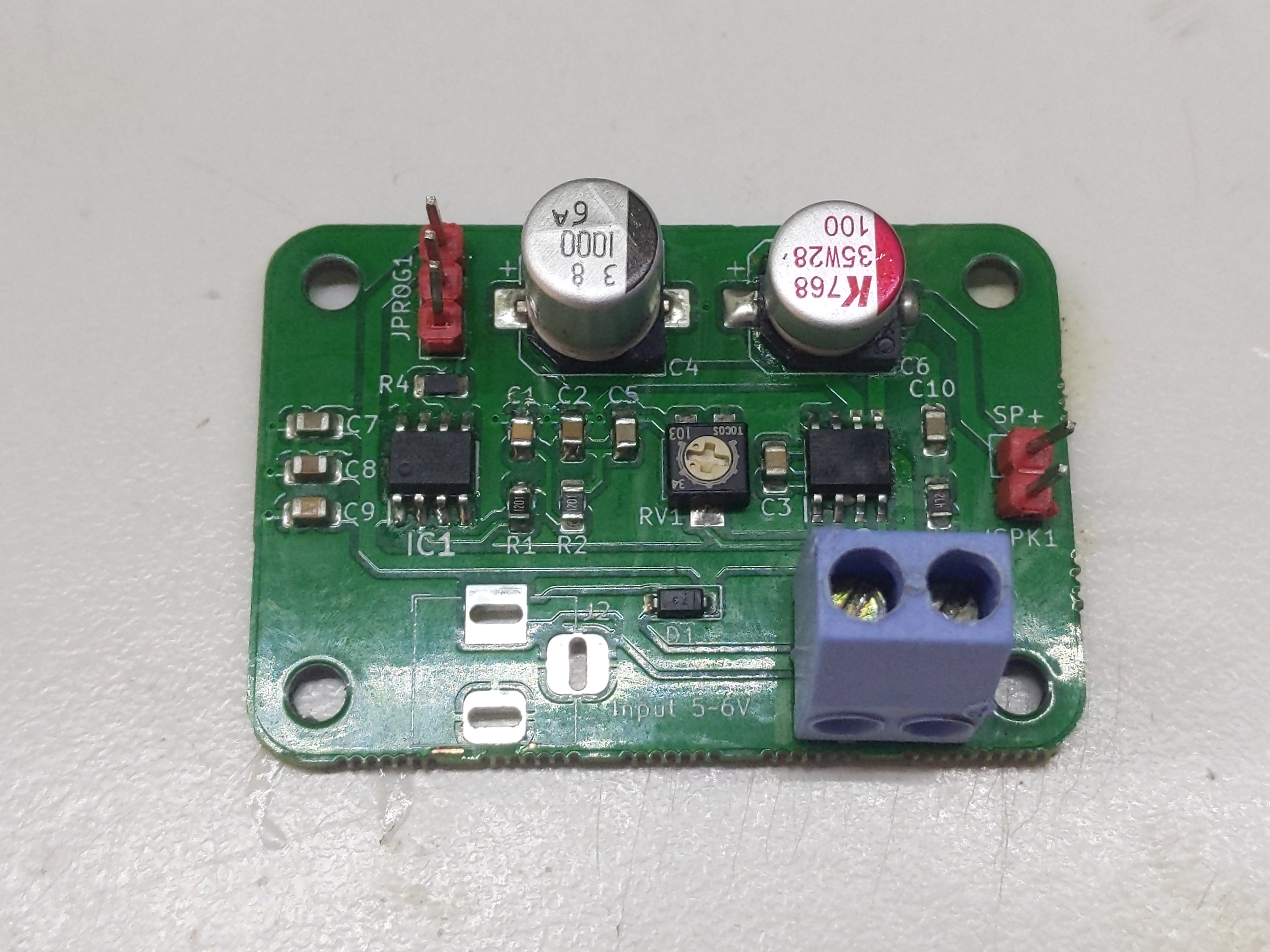
Here’s how the final sound boards ended up. Very happy about them. The Arduino Uno is only used as a programmer and voltage source for the AtTiny, so long as they are not powered by the playing field itself
A bunch of photos
