iFab - a robot assistant for our FabLab
Project date: March-May 2025
Intro
This is one of the projects I took part in as part of my job for Fondazione Mondo Digitale (and in particular, its Fablab). It was itself part of the Ital.IA Lab initiative, in collaboration with non other than Microsoft. The idea was to showcase Microsoft’s Copilot Studio platform by creating a robot which would assist new users of the Fablab, both by answering questions using a LLM and a carefully curated knowledge base, and physically guiding them around the place. That sounds like quite the undertaking. And it was, also considering we only had two months and something from project request to the RomeCup 2025, where we would have to present the project to visitors of the event, and, possibly, Microsoft executives.
What we ended up building is a completely functioning prototype of a robot assistant which might, one day, wander around our Fablab. It includes a miniature version of the place, complete of cards representing the different areas and machines, tagged using ArUco markers; a chatbot based on MS Copilot that answers questions about Fondazione Mondo Digitale, the Fablab, our machines, instruments, projects and processes, using a curated knowledge base made of technical manuals, web pages and specific documentation; a robot, which navigates the model Fablab, guiding users and visitors from place to place, and finally a kiosk with a touch screen that runs the interface to the robot and the chatbot.
The project was quite complex, with lots of moving parts. In a first for me, it was also open to students and makers alike to collaborate, and I ended up working with some people which study at the same department I do, which was somewhat strange to do outside uni projects (but like in a good way). We divided ourselves in different teams, depending on the area we worked on:
- The wiki team curated the knowledge base. The team was mostly made of high school students and less technical people;
- The vision team worked on the computer vision system that locates the ArUco markers and reports their position to the frontend;
- The frontend team worked on the frontend kiosk and the backend for the different parts to communicate;
- The robot team worked on the robot and the navigation around the space.
Can you guess which part of the project I worked on? That’s right, the wiki.
Just kidding, it’s the robot, of course. I basically custom-made the job for myself. Perks of organizing projects every once in a while. Although I had a hand in some early tests for the frontend and the chatbot, before other people joined.
Some usual faces took part in the project: Davide worked at the structure of the robot, Emanuele (not me, another one) worked on the frontend and part of the vision subsystem, Daniele oversaw everything and made sure we could get everything we needed fast. And he’s the one who put us in this situation in the first place.
Since I worked on the robot, it’s what I wanna talk about in this post. I am quite proud of how it ended up, and the techniques I used, particularly from a control theory point of view (I’m a control engineering student after all). Most of the work on the path planning and kinematic control was lifted straight out of my bachelor thesis, the rest was inspired by other experiments I did on my own and uni courses I was following at the time.
The entire project was presented at Microsoft’s stand at the Romecup 2025. Fortunately, we constantly had visitors at the stand and thus, unfortunately, we didn’t manage to get any nice footage of the project during the event. The only video of the performance is in the Gallery at the end of this post. Everything about this project can be found on its GitHub repo.
Robot
At the Fablab we have a somewhat strict and absolutely self-imposed policy of making do only with that we already have laying around, both for machines and materials. It works, since we often work on strict deadlines. It sparks creativity, I find.
In this case, however, we had to make do mostly because we didn’t have time to wait around for parts to arrive. But how hard can building a robot actually be? On paper, not that much. In practice, I spent just shy of 100 hours on this project. And that’s just me, but about ten other people worked on the project with various levels of involvement. We spent a bit of time brainstorming if making a robot was actually possible, how it would navigate around, what parts we already had available and what we could do with them.
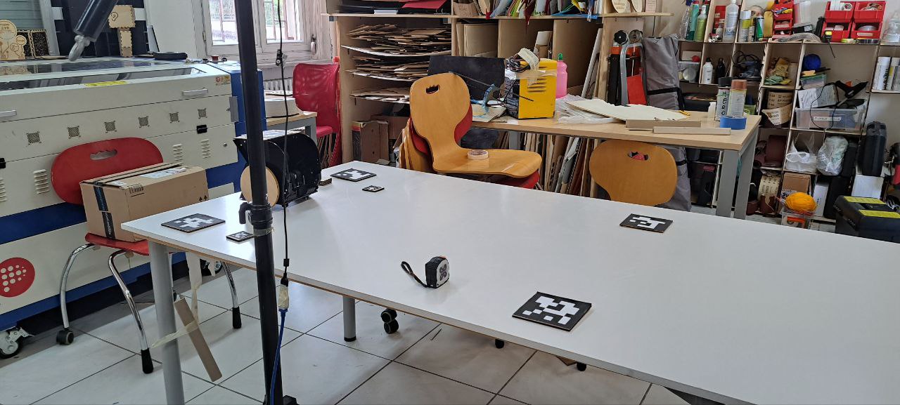
For the vision system, a workstation with a camera mounted on a tripod is more than enough. The workstation runs some Text-To-Speech and Speech-To-Text models for the chatbot, and doubles as the kiosk. For the kiosk, I had a 24inch 4:3 touchscreen monitor at home that had be laying around for ages waiting for me to do something with it. Bonus points for freeing space at home.
For the robot, I had a couple 12V DC motors with encoders and a classic L298N motor driver I was doing some experiments with, controlling position and velocity. I put them on the table (and was reimbursed later). Having encoders is nice, because it means you don’t navigate in the space completely open loop, but you can use them to at least estimate the pose of the robot. Also they allow to control the angular velocity of the motors precisely, making pose estimation even easier. The other apprach to do this would have been to estimate pose directly with the camera, with an ArUco marker on top of the robot. But the vision system would be way too slow to be used for decent control of the robot.
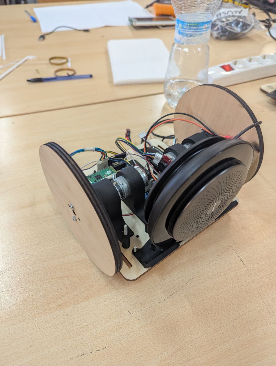
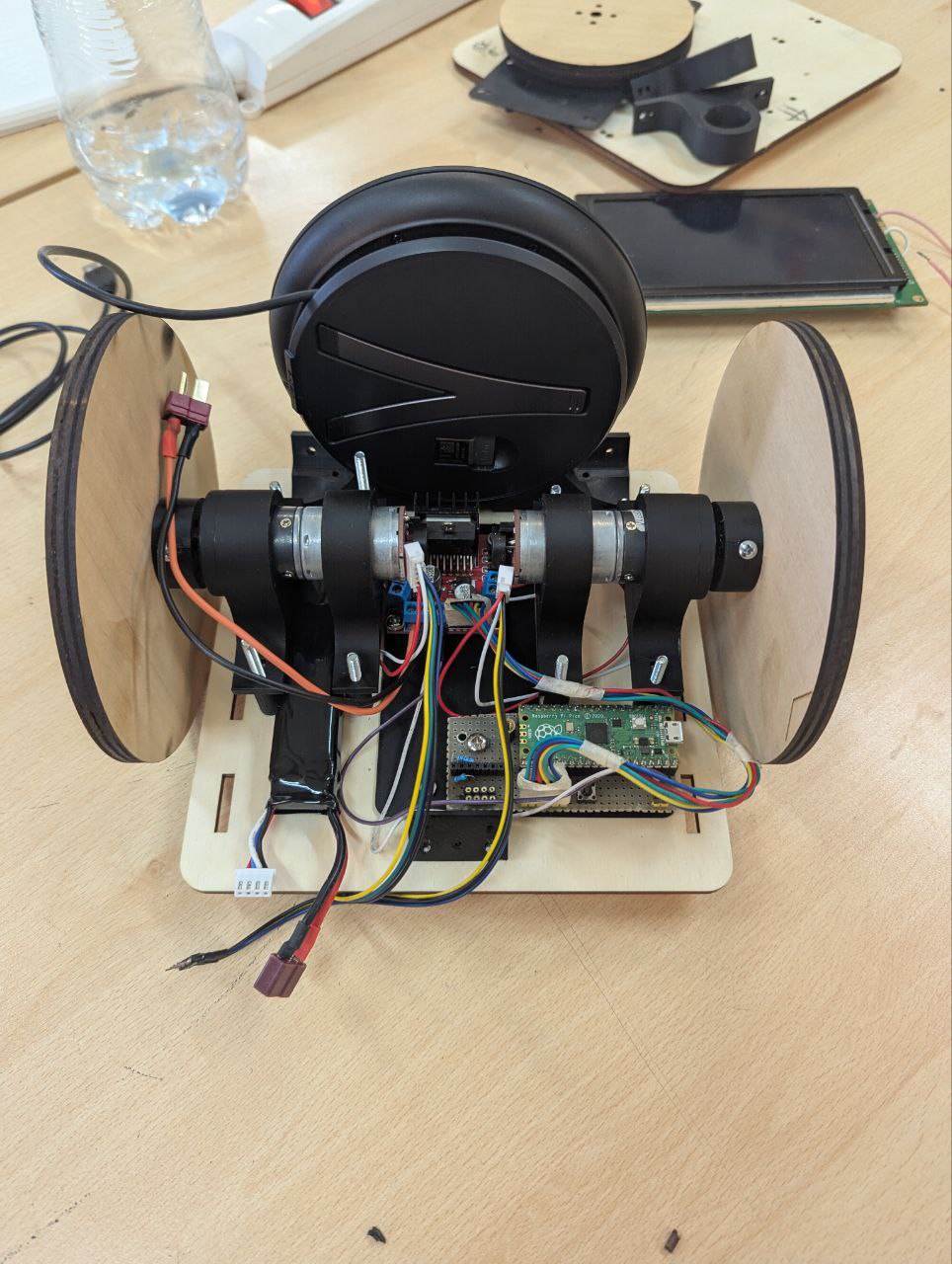
Davide gave us a basic platform to start working on in about a day. The final robot was made of laser cut plexyglass, 3d printed joints, a Raspberry Pi Pico W microcontroller with the Arduino-Pico framework, two DC motors with encoders and a L298N motor driver. All mounted inside the robot and wired using a piece of perfboard.
Kinematics
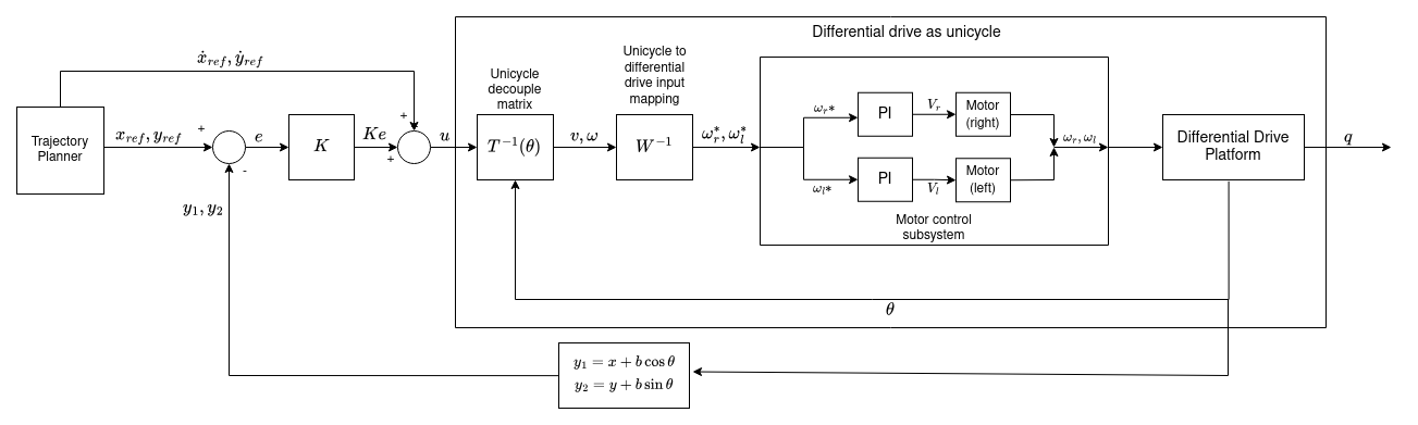
For the kinematics of the robot, we settled on a simple differential drive platform, mostly because we only had two motors on hand. Nice, simple platform that can move anywhere in the plane as well as control the orientation (or heading), but not both at the same time. I’ll come back to this point in a bit. It’s way easier instead to have it follow a trajectory in the plane, using partial (input/output) feedback linearization for example. It’s the same control technique I used in my bachelor thesis and I was familiar with it and the maths behind it. This makes the input system behave like an integrator (more precisely one integrator for the x coordinate and one for the y coordinate), with input the velocity and output the position. From linear control theory, an integrator can be stabilized using just a proportional feedback against the reference position, plus a feedforward term for the reference velocity, which allows us to follow arbitrary trajectories.
To use it in a way that makes mathematically sense though, you need to be able to accurately command angular velocity to the motors. That’s why we have two low-level PI (Proportional-Integral) loops that control the motors (one loop for each motor), running at 5ms. I used the amazing pico-encoder library, which uses the Pico PIO (Programmable IO) to read quadrature encoders without wasting CPU time. PIOs are an amazing feature of the Pico series of microcontrollers: they are basically little programmable Finite State Machines which run independent of the CPU. They are perfect to communicate with interfaces with strange digital protocols and stuff like encoders. I really should get around to properly learn them one day.
With the motors taken care of, trajectory tracking is just a matter of actually planning a trajectory, inverting the decoupling matrix of the robot and commanding the motors. Below is a little block scheme of the whole control system. The hard part is actually defining the trajectory and knowing where the robot is to track it.
Localization and the field
This is, loosely speaking, the process of estimating where the robot is (in this case, in the plane). We used a technique called odometric localization, which takes the mathematical model of the robot and numerically integrates it (starting from a know initial location and with known inputs) to estimate where the robot currently is.
It works, at least for short periods of time. Over time however, the estimated position strays further and further from the real one, mostly because of numerical integration errors, biases, errors in the initial guess of the location, non ideal inputs, wheels slipping, etc. It’s not really a problem though, because we have a camera overseeing everything that happens in the model Fablab and can accurately compute where the robot is compared to fixed landmarks, so we can replace the inaccurate estimation done via odometric localization with the more accurate one done by the camera as soon as it is available.
We later found out, that the whole vision system is much more sensitive to vibrations and disturbances that we initially thought. In hindsight, we should have taken the time to implement a little Kalman filter for the localization. Oh well, we’ll do that for the real thing.
As for the field, it’s a rectangle delimited by four ArUCo markers. The dimensions to correctly map for camera space to world space can be set in a dedicated configuration file. There are different work zones and machines throughout our model Fablab, each one is also indicated by a unique ArUCo marker. A camera is put on a tripod so that it can always completely see the field. The robot also has a marker on top so that periodically the estimation done with encoders can be adjusted for errors.
Navigation
This project was only a prototype, so we decided to make our own life easier and say that in this version there are no obstacles in the Fablab, and machines and working areas that the robot can reach are all layed out along the sides of the scale model. The latter is a reasonable assumption to make, it’s actually how the place is layed out IRL. The former, let’s say, erm, less so. There surely would be people in the real place, and tables at the center for people to work on, and chairs, and stuff all over the place. As I said, we can make the rules around what we can actually realize.
So, to make our life easier, the robot will only follow straight line trajectories, from point to point. These are computed on the robot, online, each time the kiosk sends it a new destination. They are parametrized in space (as in, not in time) and follow a bang-coast-bang profile in acceleration, so the robot slowly gains velocity at the start, settles at cruising speed for some time, then decelerates until it arrives at the desired position.
Notice that technically the differential drive has a state composed of three elements $(x,y,\theta)$. The first two are the position in the plane, the last one is the orientation (or heading). It only has two inputs though: the angular velocity of each motor $\omega_r, \omega_l$. It is, strictly speaking, and underactuated system, because it has more state components than inputs and thus we cannot bring all three components of the state to a desired configuration at the same time. It is generally not considered as such, because orientation is often ignored as a control variable of interest, and only $(x,y)$ are considered. That’s what’s happening with this robot as well. If we only consider the problem of trajectory tracking in the plane, it’s as easy as planning and generating the proper reference velocities and position and passing them to the appropriate controller described in the kinematics section.
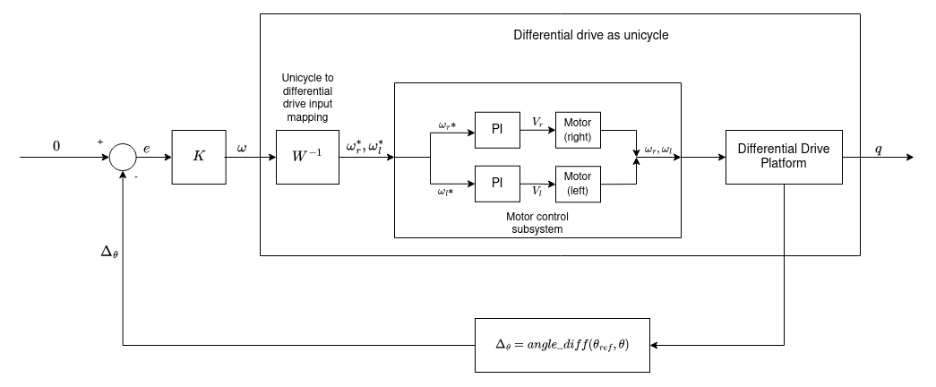
Once we get to the destination, we’d also like to orient the robot to point towards it, as it makes the whole interaction of the robot being a tour guide more realistic. Since I was following the Hybrid Systems course at uni at the time, I decided that orientation should be have an ad-hoc controller. This is done by taking as output the orientation $\theta$ of the robot and as only input the steering velocity $\omega$. Again, the robot behaves like an integrator, which can be stabilized with a proportional feedback. The only notable thing here is that the output of the system is the angle difference between the current heading and the desired one, and the setpoint of the controller is set to bring this difference to zero. This is done to properly manage the wrap-around of angles, taking into account that angles that differ by $2\pi$ are equivalent.
How the robot switches between controllers depends on the commands received from the kiosk and from the frontend. I think cartesian regulation would also have been a valid solution to the problem, and it would have required just one controller, avoiding all the stability concerns that stem from switching between two controllers in a discrete manner. The point here is that we really wanted the robot to have a predictable and programmable behaviour during transients (that is, when we’re reaching the destination), lest we crash in some wall. By using the tracking techniques we did, we were able to follow pre-planned trajectories, also giving the robot more natural behaviour in the eyes of the users.
Another way to avoid having two different controllers would have been to add a via point, and plan a continous trajectory across that point that would also allow the robot to end up with the desired heading. I don’t exactly remember why we didn’t do this, I think it was some kind of problem on actually computing the via point on the vision subsystem part, I would have preferred this solution.
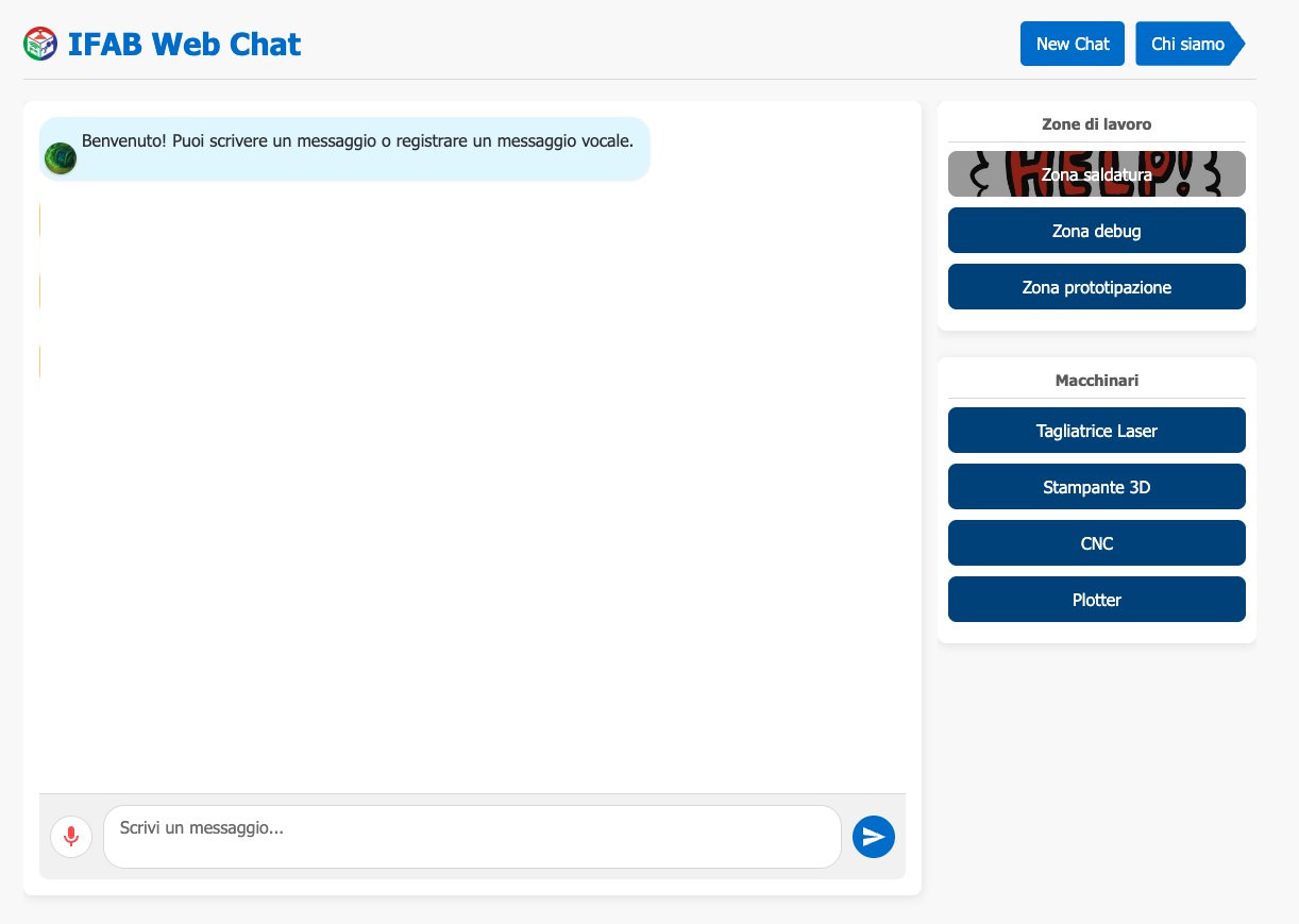
Kiosk interface and selecting a destination
The kiosk has an interface when the user can either text or record voice message to send to the chatbot. The answers are computed using a bot made with MS Copilot Studio and our knowledge base, and the responses shown in the interface. Talking with Copilot Studio was an adventure in and of itself, thanks to Microsoft barely existing documentation on the subject and less than stellar API. Emanuele did most of the (colossal) work on this, setting up the very finnicky websocket communication with Copilot Studio and intercepting messages to show in the interface. I only did some preliminary tests with this, and to me the whole interface didn’t really seem thought to be used in scripting or as an API at all.
On the right of the user interface there’s a series of buttons, each indicating either a work zone (electronics, prototyping, materials storage) or machine (3d printers, laser cutters, cnc mills…). These are identified by unique ArUCo markers printed on some cards placed of the field. When a user clicks a button, the pose of the corresponding card is identified, as well as that of the robot. The pose is always computed against four fixed landmarks placed a the corners of the field. These coordinates are then encoded in JSON sent to the robot over UDP, which uses them to compute the trajectory and track it.
Full control architecture
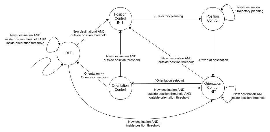
The full architecture is that of a hybrid system, represented by the Finite State Machine in the diagram below.
The robot starts IDLE, staying still in the position it is currently at. When a new destination is received from the frontend, the robot first checks if it is already near the position. If it is, it doesn’t move, but eventually switches to ORIENTATION_CONTROL if the desired orientation is outside a threshold from the current one. This is useful when the user selects a new target which is close the old one, or selects the same target twice.
If instead the destination is far away enough from the current position, the robot computes the straight line trajectory and starts following it, switching to the POSITION_CONTROL state. If a new destination is received when the robot is moving only the setpoints are changed, without stopping and accelerating again like it would if starting from IDLE.
Once the destination is reached, the robot switces to the ORIENTATION_CONTROL state, aligning it heading with the destination. Again, if a new destination is received while the robot is in this state, only the setpoints are changed, without changing state.
Once it is pointing to the destination, the robot goes back to IDLE.
In between the IDLE state and either POSITION_CONTROL or ORIENTATION_CONTROL, as well as the two controller states themselves, there are two initialization states that properly reset the controllers and auxiliary variables.
Trajectory tracking and heading control are each performed by means of a partial input/output feedback linearization scheme.
Gallery
iFab:
(audio in italian)
References
Most of the stuff I treated here (feedback linearization, the modeling of mobile robots, input transformation between DDR and unicycle) I knew from working on my bachelor thesis and I studied on materials for an exam I attended during the final semester of my bachelor: Applicazioni dell’Automatica. That exam itself was a condensed version of the Autonomous and Mobile Robotics course I attended at uni last semester. The rest of the topics I treated come from different contol theory courses I attended in the course of my accademic career.