Project date: November-December 2025
Intro
For the past couple of months I have been trying to make my own PCBs, using the laser engravers we have at the Fablab. Other makers had tried before, with poor results. It’s as if a slight greasy patina would remain on the board after engraving, making it impossible to actually etch away the copper using acid. After about 4 weeks of experiments (the fablab is open only on Saturdays), lots of advice from other makers, and a decent quantity of youtube videos and Hackaday articles on the subject, I managed to arrive at a reliable process to make my own PCBs.
Experiments
Let’s start with the specifics. At the Fablab we have two different Co2 laser cutters/engravers: a Workline Model 1290 with a 100W laser and a LaserWorks LW-Mini with a 45W laser. Neither lasers are powerful enough to directly engrave the metal, so another approach has to be taken.
The needed materials were already present at the Fablab, notably the FR4 boards themselves and the Ferric Chloride, probably used by other makers that visited the Fablab eons ago. The availability of the materials is what convinced me to try make my own PCBs in the first place, actually.
The method I use, which is quite common, is to first coat the board with a thin layer of black acrylic spray paint, then use the laser to selectively remove the paint, exposing only the areas where there should be no copper on the final PCB. Finally, the board is placed in a bath of acid. I use Ferric Chloride, because it’s what was already at the Fablab, but there exist alternatives, like sodium perclorate, ammonium perclorate and sodium persulfate. Throughout this post, I will use the words ferric chloride, etchant and acid interchangeably.
Previous attempts used the Workline at full blast, but from my research I saw lots of people using cheap low-power diode lasers, down to 2.5W, but usually more around 10W. I tested different velocities and powers in a grid and carefully noted the results for each setting, starting at 10mm/s and 10% power and slowly ramping up until the material didn’t come away completely. I also tried some post-processing steps, like delicately rubbing the engraved area with a q-tip slightly wet with water. This seemed to remove some residue on the board. Notably, IPA cannot be used for this as it dissolves the paint, including the parts you want to stay on the board.
Grid test pattern
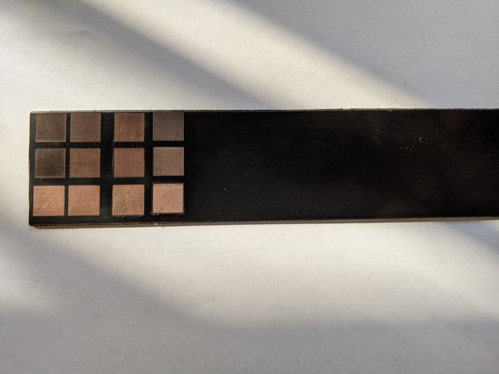
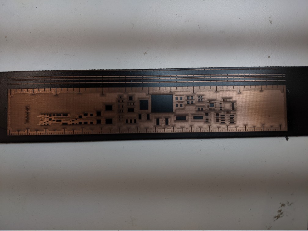
When I was satisfied, I tried putting the board with the test pattern in acid, to see if it would actually etch. It did, so I was happy and started trying to make some actual PCBs. I used the Adafruit PCB Ruler as a test so see what features I could obtain. Not very good apparently, and it turns out the LW-Mini is in dire need of a mirror realignment. You could actually by the naked eye that the laser dot was waaaaay too big, even when in focus.
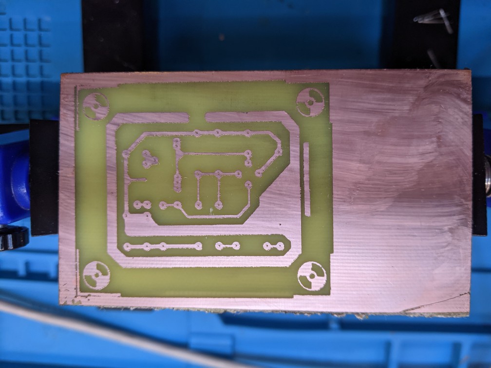
However, I did manage to do a PTH-only PCB with quite thick traces, for my father’s Elektor Pong build. This was a particular nice result for me, as I managed to go from a high-resolution scan of an old magazine my father made to a finished PCB in just under a couple of hours.
Adafruit Ruler
Elektor Pong
Putting the mirror realignment to one side for a moment, I tried repeating the process on the Workline, now knowing that a low speed and laser power were key. I crashed head first into that pesky greasy patina on the board.
After a couple of weeks of experiments and with precious advice from the maker Ugo, I managed to boil it down to two causes: oxide and grease. The former certain: I could actually see some sparks when working on the LW-Mini. My explanation is that the laser being out of focus on the LW-Mini somehow managed to remove parts of the oxide, especially at slower speeds. This is easily solved by using very fine sand paper on the board before coating it with paint.
The latter is still only a supposition, but it makes sense. We suspect two sources of grease: the first from whatever it’s on the board already, including skin oil from handling the board and touching the copper. You can actually see fingerprints on the copper, and surely that’s not good. The second we think comes from the paint itself, as a residue left behind when it’s burned by the laser. We also suspect that a too strong air flow from the compressor during engraving actually causes the paint to not evaporate properly, remaining on the board. This is solved by treating the board with some degreaser (the kind you’d use to clean the kitchen) before coating it with paint and after removing it with the laser. Maybe dish soap works too, we are yet to try it. When using degreaser and a q-tip after burning away the paint to clean the paint, you can actually see the greasy patina coming away and leaving the shiny exposed copper behind.
Complete process
After many tribulations, I managed to come to a complete, reliable and reapeatable process. What follows is mostly an English translation of the dedicated section I wrote for the Fablab internal wiki.
Start by thoroughly cleaning the copper with very fine sandpaper to remove any oxide. The board should be slightly wet to make it easier. I use 800 grit sandpaper.
Cover the board in degreaser and leave it for about 5-10 minutes, to remove any oil or grease. But make sure NOT to touch the copper with bare hands from now on, to avoid leaving skin oil on the copper
Clean the board with running water, then dry it with paper or a towel. From now on, when i say “paper”, I mean something like toiler paper or paper towels. It should be soft and able to absorb water.
Coat the copper side with a thin and even layer of black acrylic spray paint, preferably matte. Shake the bottle for around a minute before coating.
Wait for the paint to dry, then use some paper to remove any dust that may have deposited on the board meanwhile.
Use the laser engraver to remove the paint from any spot you do not want copper to be on the final board (i.e. anywhere that is not a trace or a pad). Tuning speeds and power depends on your machine, as well as the software used to prepare the machine job. In general this is done by running an engrave job on a DXF file or a black and white image of the copper layer of the PCB.
- I use KiCAD, and export the copper layer F.Cu and the board margins EdgeCuts in DXF from File>Plot. Then import those into the laser cutter software.
Remove the board from the machine, then cover it again with degreaser and leave it for about 5 minutes. Then, clean the board gently with a q-tip or a very soft brush. You should see a greasy patina come away, and then board will appear cleaner since the copper is now actually exposed. Pay attention not to rip away any paint with the q-tip. Also do not use alcohol to clean the board, as it dissolves the paint (IPA in particular).
Dry the board with paper. DO NOT rub, to avoid removing paint.
Etching: Put the board in a bath of Ferric Chloride or equivalent etchant to remove the exposed copper.
- Use protections, like gloves and glasses. Ferric chloride stains the skin and clothes, and cannot be removed. Ask me how I know. If you accidentally splash it on something (including your skin), use wet paper or towel to quickly remove it.
- Use plastic or glass containers for the etchant, metal containers will be corroded just like the copper on the board.
- You can use some long strips of adhesive to maneuver the board, just make sure not to cover the portion you are etching with the tape.
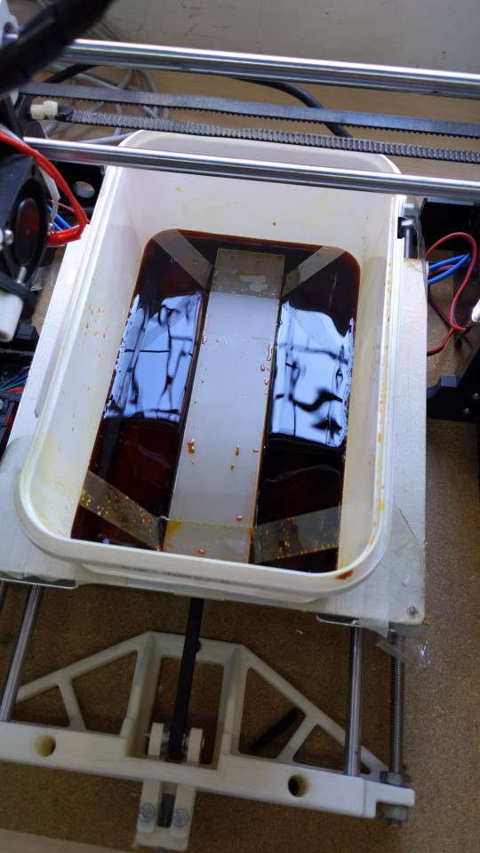
- The time needed and the final product will depend on a number of factors: ferric chloride likes to be warm (I use about 50°C) and stirred. If done well, etching should take about 10 minutes. On the other hand, it took me more than a hour to etch one of the test squares with a cold (20°C) and not stirred etchant.
- I use my old Anet A8 3D printer (bed slinger, with a moving Y axis) to do the warming and stirring. I used gcodepy to create a gcode that warms the bed to 50°C, moves the extruder out of the way and makes the bed move back and forth following a sine wave for stirring.
- Do not leave the board in acid too long, or even the areas with paint on top will become exposed and will be etched away (underetching)
When done, remove the board from the acid bath, and use slightly wet paper to remove any residue.
Use acetone to remove the remaining paint from the board, exposing pads and traces.
Cut your PCB to size, removing excess margins. I use the back side of a Stanley knife to define the cut on the board, the snap it using the side of a table.
We’re done! Congrats!
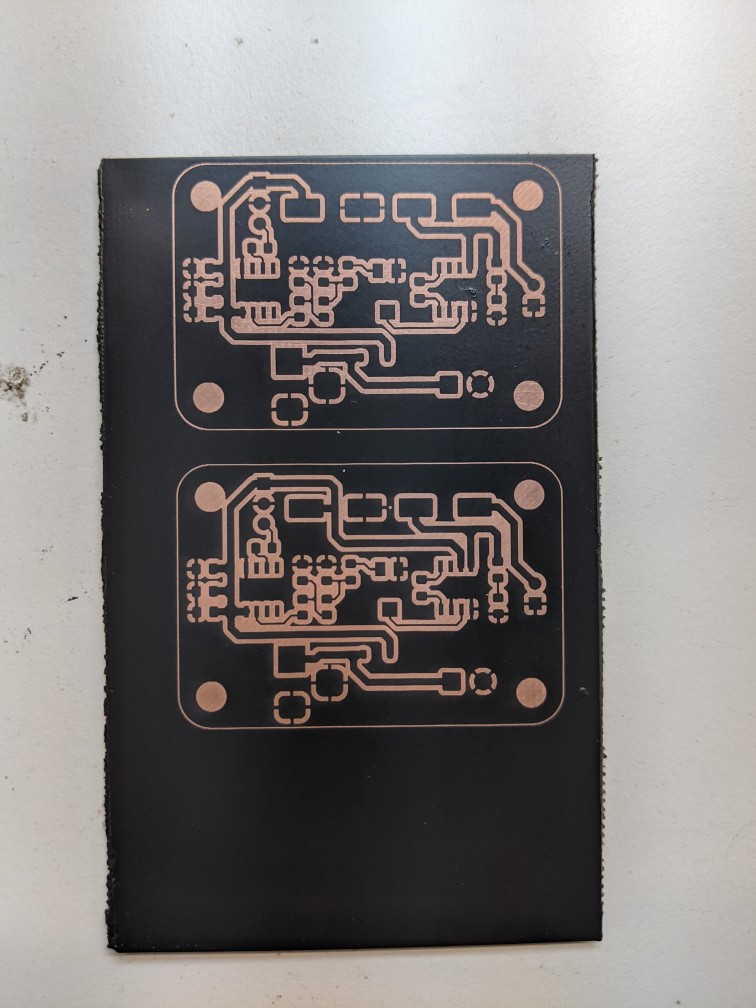
Acid bath
The PCBs I made for the RomeCup 2024
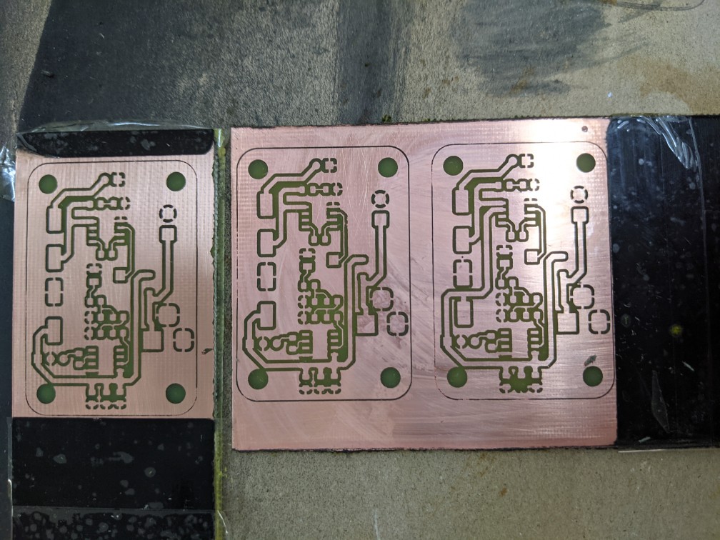
The PCBs before being etched and before removing the greasy patina
Machine parameters
These are the parameters I use with both machines. Maybe they’ll work on similar machines, or use them as a reference and experiment with your own machine.
Workline Model 1290
- Engrave job
- Speed: 350-450 mm/s, depending on the size of the features
- Unilateral sweep (the laser is activated only when going in one direction in the pass. Using it for both passes overetches the paint, probably because of vibrations in the work plate).
- 2-3 passes. 2 are enough in all the experiments I did up until now.
- Power 30% (on a 100W laser)
- Air flow 0.75 kgf/cm^2. We suspect too much air flow prevents the paint from evaporating completely, contributing to the greasy residue. We still need to have some air flow to prevent the smoke from the paint from going on the laser lens.
LaserWorks LW-Mini
- Engrave job
- Speed 20-50 mm/s, depending on the features
- Unilateral sweep (this time because it’s out of focus)
- Power 15-35% (on a 45W laser)
- 1 Pass
- We cannot control to air flow with the compressor on this machine, but it seems to be low enough not to cause problems
Future work
I’ve had some success in using the Eleksmaker A3 2.5W engraver I have at home for exposing copper on a board. It’s slow, but it seems to work. However I still haven’t tried making a PCB with it with the complete method.
The method I described should work, in theory, even for double-sided PCBs, but we currently lack templates for the laser engravers to correctly align the two layers. We are working on them, as well as templates for our CNC mill to drill holes for PTH components and to cut the boards to shape.