Designing very small robots
Project date: Autumn 2023 - ongoing
There’s this project me and Davide have been working on on and off for at least a couple years, being only able to put a some hours into it once in a literal blue moon.
We are taking very small steps, but slowly but surely we’re getting there. The project is a game, which is played by piloting remotely controlled robots through a very peculiar path. Due to design constraints in the path itself, the robots need to be as small as possible, or the whole playing field easily becomes huge.
I ended up developing my first 4-layer PCB for it.
While the project is not ready yet, for MakerFaire Rome 2025 we decided to repurpose the robots for BotRoyale, a capture-the-flag game we built in a single weekend.
In this blog post I’ll go through the design decisions for the PCB itself and for the rest of the robot. The constraints were few but significant:
- the robots had to be as small as possible, as the path is heavily dependent on the width of the robot, and the additional space requirements add up quickly;
- the robots need to be as cheap as possible, as we need to build multiple for the game to be functional, and we are financing the project ourselves;
- The robots need to be battery powered and remotely controlled, either by wifi/bluetooth or something else with low latency. Bonus points if the microcontroller also handles battery charging;
- Possibly dipswitches for configuration of different features at runtime, and a general switch to turn off the entire robot without needing to disconnect the battery.

The Codecells by microbots.io have all the characteristics, have a decent price, and they were our parteners at MFR2025. While I learned about them from some of Carl’s youtube videos before starting this project, I kinda forgot about it until after I was ready to order PCBs. Still, I reckoned even the light version with no IMU was too expensive for us, considering we wanted to build at least 8 robots. From their shop, the Light version costs 12€, but doesn’t seem to have a motor driver. The Drive version does, but also costs more than twice as much. And that’s only for the microcontroller, we would need to buy motors and batteries externally. Plus, it would still lack configuration switches and a general power switch, which we need for easy management of our game.
I’m totally not complaining about the price of the Codecell, it’s really good for the package, but in this case I need much tighter control on the design specifications than the Codecell family would allow. So I’m building my own.
PCB
After a bit of scouting, I decided to base my own designed around the Seeed Studio XIAO ESP32C3. It features an esp32c3 microcontroller with external antenna for wifi and bluetooth, as well as lipo charging circuitry with voltage regulation on board that can source up to 700mA.
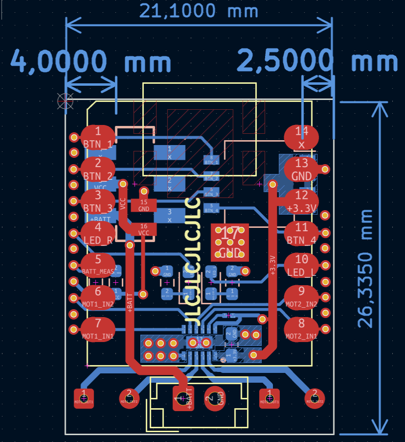
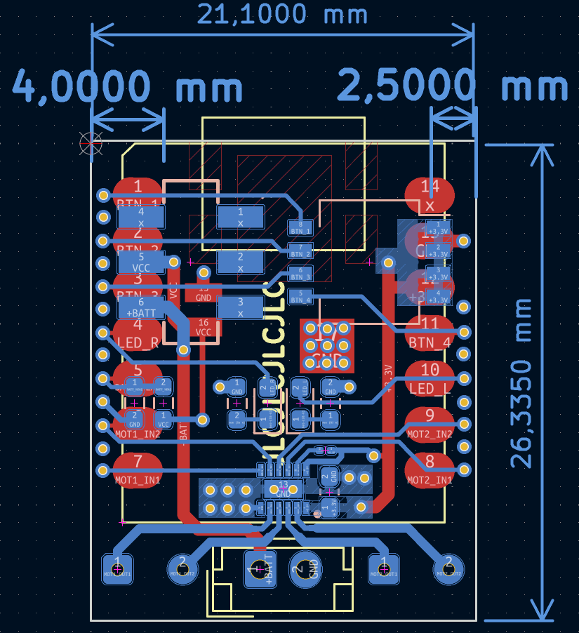
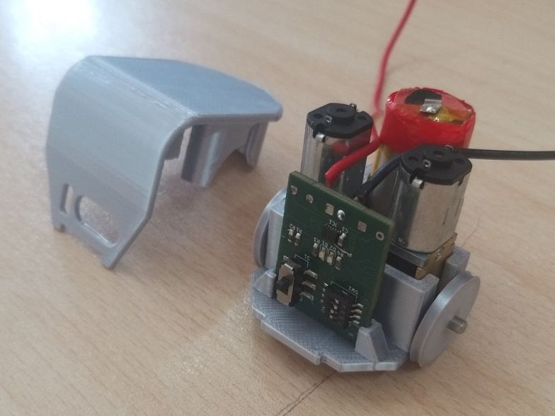
I started by designing a double layer PCB. One side has the XIAO surface mounted. On the other side, the top portion features dipswitches for game configuration and supply switch. In the middle, I put the LEDs for status displaying (such as robot id, or charge status). Following Seeed’s documentation, I also made a voltage divider with two 220kOhm resistors, with the middle going to the ADC to read battery voltage (though I have not implemented it yet).
The bottom portion holds the motor driver. I went for a Texas Instruments DRV8833, which is a dual h-bridge driver, sourcing up to 1.5A, but the motors we went for sank at most 400mA each. For the layout of our PCB, the 16-Pin HTSSOP package was the one that made the most sense, mainly because the inputs are all on one side and the outputs all on the other. The remaining space on the board was used as thermal pads for the motor itself, directly to the ground plane.
For passives, I decided to go for the 0603 package, as they are sensibly smaller than 0805 but I can still solder them by hand. The final footprint is barely more than that of the XIAO itself, only going a bit further in the bottom for the battery and motor connectors.
After finishing the first layout, I noticed that there was basically no space for a continuous ground plane because of all the traces. I sought advice on Lemmy and was suggested to use a 4-layer stack-up. It was something I had never done before, so I started looking online. In particular, I landed on Phil’s Lab youtube channel. He has great video on PCB and microcontroller design. In the end, I decided that the two internal layers should be both ground, and the two outer layers for signal and supply. I did this to ensure both signal layers would have the return to ground as close as possible, and that both layers would have their respective ground plane at the same distance a the other. The two ground planes are then connected with plenty of vias.
Another popular approach seems to make one of the middle planes ground and the other supply. From my research, this tends to be considered wrong because one plane references ground while the other references the supply voltage. Furthermore, of the external layers, one would have a closer return to ground than the other. Moreover, in my specific case, I do not need to do complex routing for power tracks, as there’s only a couple of traces going from the battery to the microcontroller, and from the microcontroller to a couple components.
Manufacturing
I had the PCBs manufactured by JLCPCB. I also had them assemble the bottom side, as it was cheaper than buying and assembling the components myself. Since they did not have the XIAOs in stock, I ordered them separately and soldered them myself. It was also my first time soldering components with thermal pads on the bottom side. I didn’t order stencils from JLCPCB since they would greatly increase shipping costs. I built my own stencils with the method described in the relative note, which I have update with photos of the PCBs and the stencils.
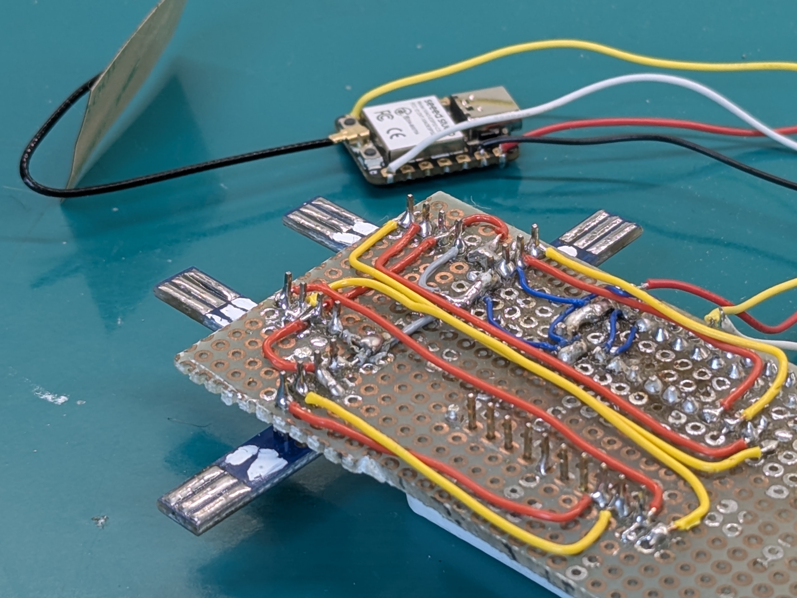
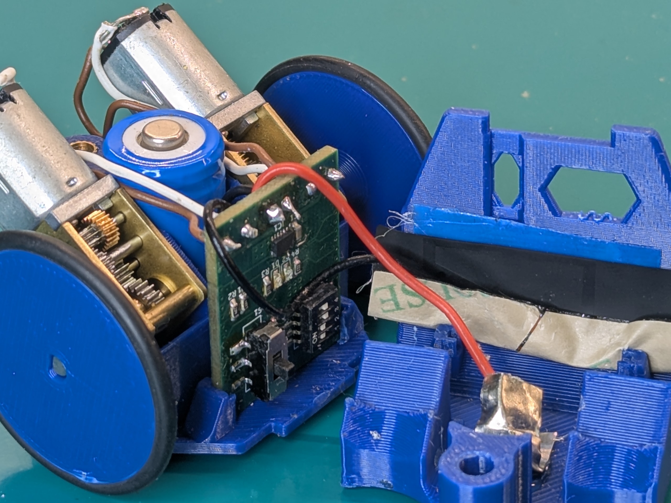
The real problem with assembly were the battery and the motors. For the battery, I soldered wires to nickel strips and glued them to the chassis. We left way too little space for the wires in the chassis, and it was hard to maneuver them around. I was also using whatever wires I managed to find around, and most of them were either not flexible enough or of terrible quality, so they tended to break often when debugging and working on the robots. We also didn’t consider than the XIAO need external antennas, so we had to kinda force them to be inside the chassis.
To bring the cost down, we initially tried using batteries from used vapes gifted from friends, but we found too much variability in sizes. We ended up using 14250 batteries, which we got for cheap (16€ for 12 batteries) on aliexpress. These are commonly used in smoke alarms and carbon monoxide detectors, hence the much lower price compared to other formats. Remember that for us keeping the price low is more important than making the robots small.
First batch problems and what I’d do differently in hindsight
As usual, the first iteration never works perfectly well.
On the less severe problems, I inverted the labels for right and left motor with respect to the schematic. No big deal, I remapped them in code. I also totally missed that the motor driver has a sleep pin, which is active low. I didn’t connected the pin to 3.3V, which meant the driver was never active and the motors never spun. For that, I simply soldered a wire going from the sleep pin to the nearest available 3.3V pad, which happened to be on a jumper pad I predisposed to switch between the motor PWM and Phase/Enable mode switch pin. I have become quite good at soldering wires on such small pins by hand, if I may say so myself.
The rest of the problems I think are relatively serious, but in our extensive testing didn’t seem to harm the hardware. The first is that the XIAO needs an external antenna. At first, I tried using it without. I could get decent range when using my laptop as a base station for our game, but I didn’t have such luck when using a Raspberry Pi Zero. As I learned in my recent endeavours with setting up a meshtastic node on my balcony, when not using an antennas there’s a chance part of the signal reflects back onto the antennas itself, at the risk of damaging the radio module. Maybe this only happens at the sub-GHz frequencies of LoRa, maybe I got extremely lucky. I don’t know RF enough to judge that. Anyhow, we connected the provided external antenna and then proceeded to struggle manfully to make it fit into the chassis.
Another thing that really bugs me is that at some point I noticed I was supplying the motors from the regulated output on the microcontroller. This was a conscious choice: I even did the computations to check if I would be within the current limits on the regulator: each motor stalled at 400mAh and the regulator was able to supply up to 700mAh. I decided it was ok because the motors “would never stall in this application” and went with it, because I really did not want to add an external regulator and take more space on the board. In this case it would have been better to supply the motors directly from the battery, with no risk of damaging the regulator with overcurrent. While the motors are rated for 3v, slightly overvolting them at 4.2V with a fully charged LiPo wouldn’t be a problem. Present me facepalmed hard at past me’s decisions.
I also totally missed adding bulk capacitors for the motors. Still, it seems that everything works without, so I guess either the capacitors after the regulator in the uC are enough, or the motors absorb current little enough (and most importantly, there are no important jumps in speed/directions that require additional capacitance.
Apart from fixing these problems, one thing I’d add in a second revision is a boost converter to possibly supply the motors with higher voltages: our 3V motors work fine enough, they have low torque and are easy to stall if anything. I think faster motors would probably give a more satisfying experience overall, but would need to be supplied at 6 or 12V. We were also debating whether it made sense to switch to plain ESP32C3 mini’s, like the ones used in the Codecell. These are smaller than the XIAO, cost half as much and have onboard antennas, but they lack the battery charging circuit and a USB port for programming, which would need to be add separately. It all comes down to being able to squish the components in at least as much space as in the current boards, if not less. And if they can be made for the same price, if not less.
Mechanical design
Davide managed the mechanical design and assembly of the robots, all the iterations. This section was written by the man himself, with some minor editing by me.
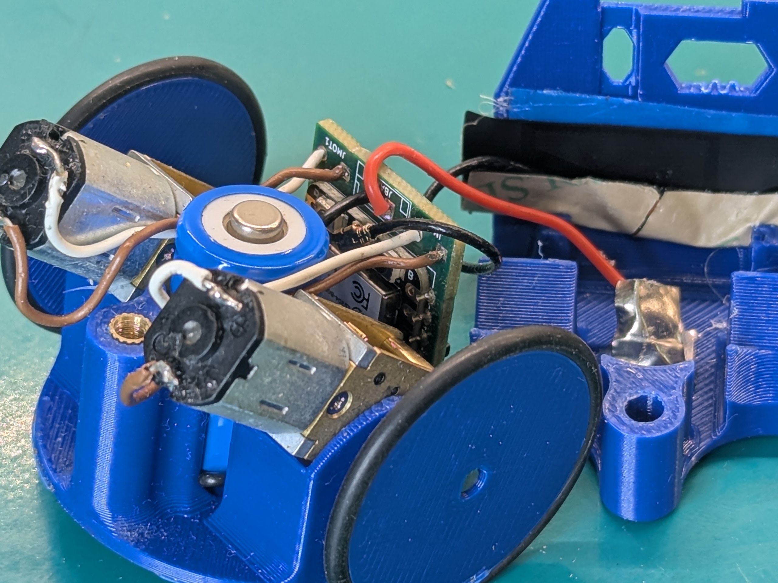
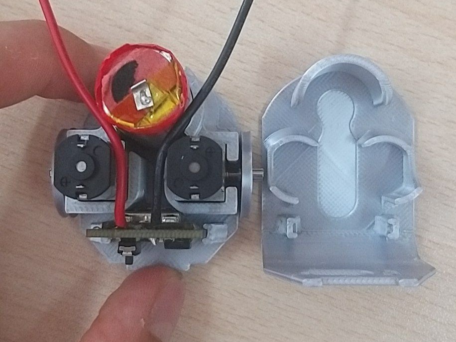
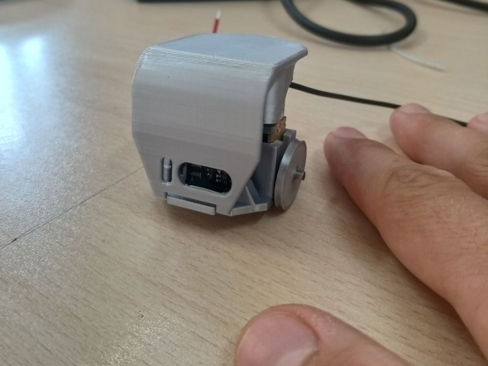
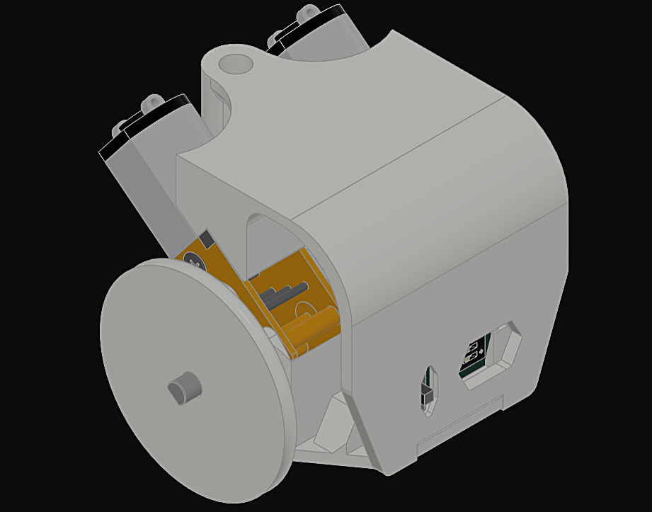
One evening an idea came to me about a simple structure, and from that evening the original design came out. Nothing special, it was (and in fact, it is still today) a simple two pieces assembly which was able to keep the PCB in his place as well as the motors and the vape battery we were using. All of the chassis parts were 3D printed in PLA and PETG. The bottom part has all the slots to insert the components, while the top part acts as a cap to lock them, then the overall is closed by a simple screw. The cap included also two front holes to manage all the PCB’s switches.
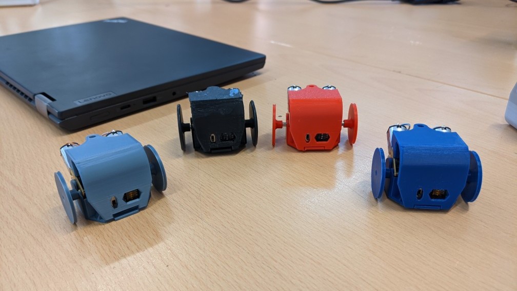
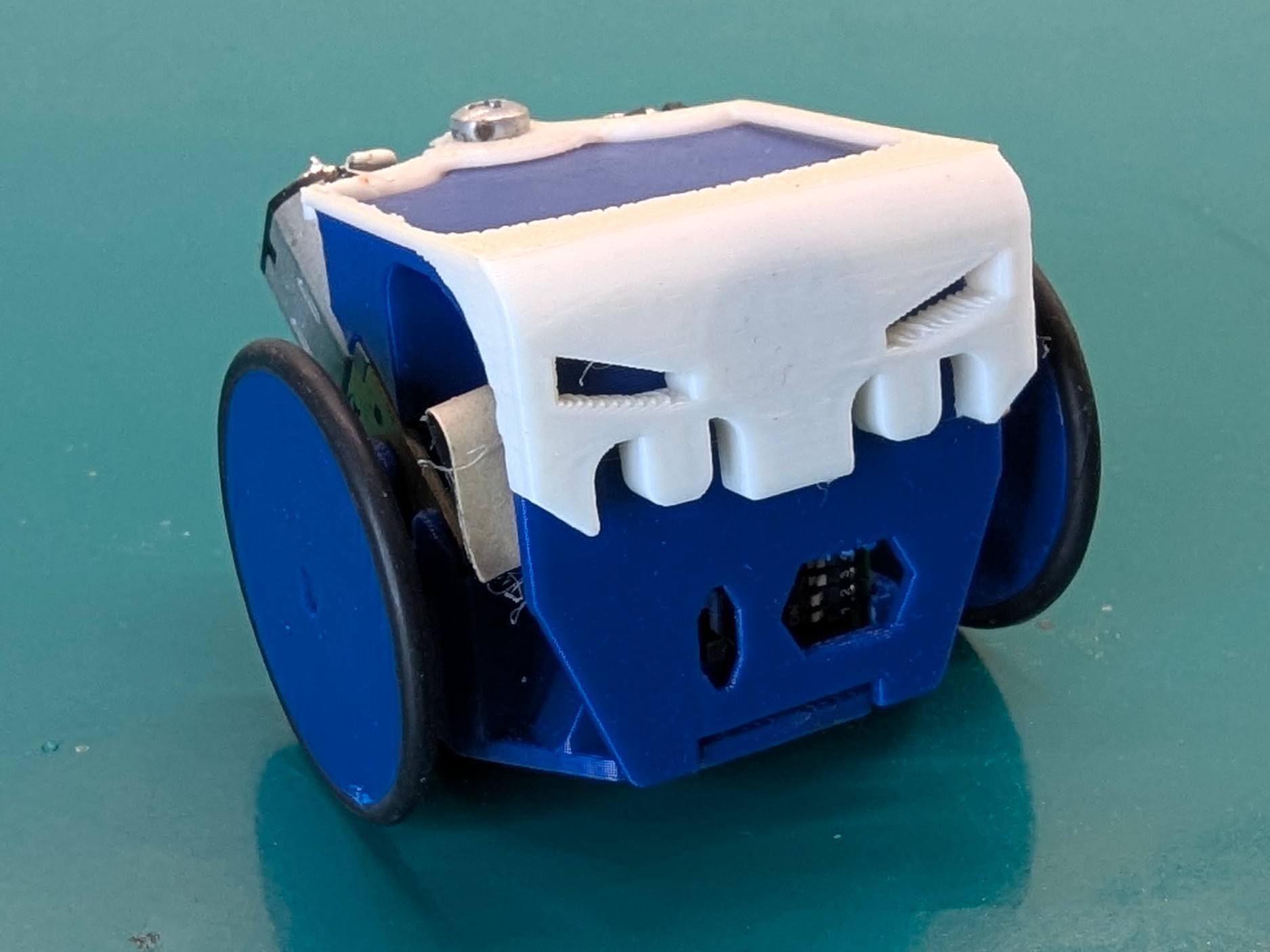
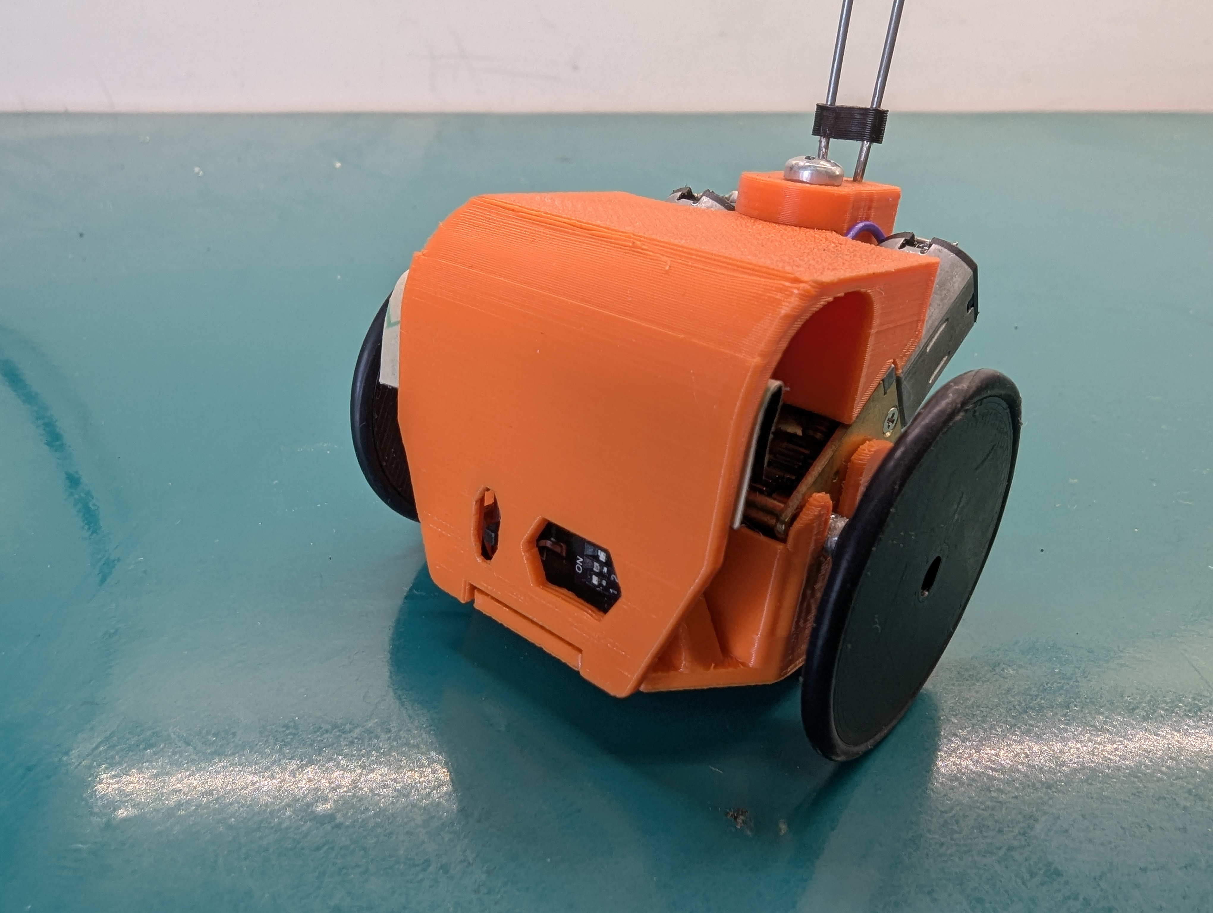
At the time we just looked at it just as something cute, but it was too tall, too large, and most importantly too slow for out upcoming project, so I worked out the second generation -named speedster- to fill some gaps of the first one. The next one featured tilted motors, larger wheels and support for the specific 14250 battery since the ones taken from vapes, as already mentioned, vary too much in sizes (and capacity). Bigger wheels makes it faster (literally a speedster, also I watch The Flash too much) at the cost of a smaller output torque. The tilted motors allowed the design to be shorter while just expanding a bit behind, thanks to them the speedster also obtained a much cooler look, a characteristic I care a lot about.
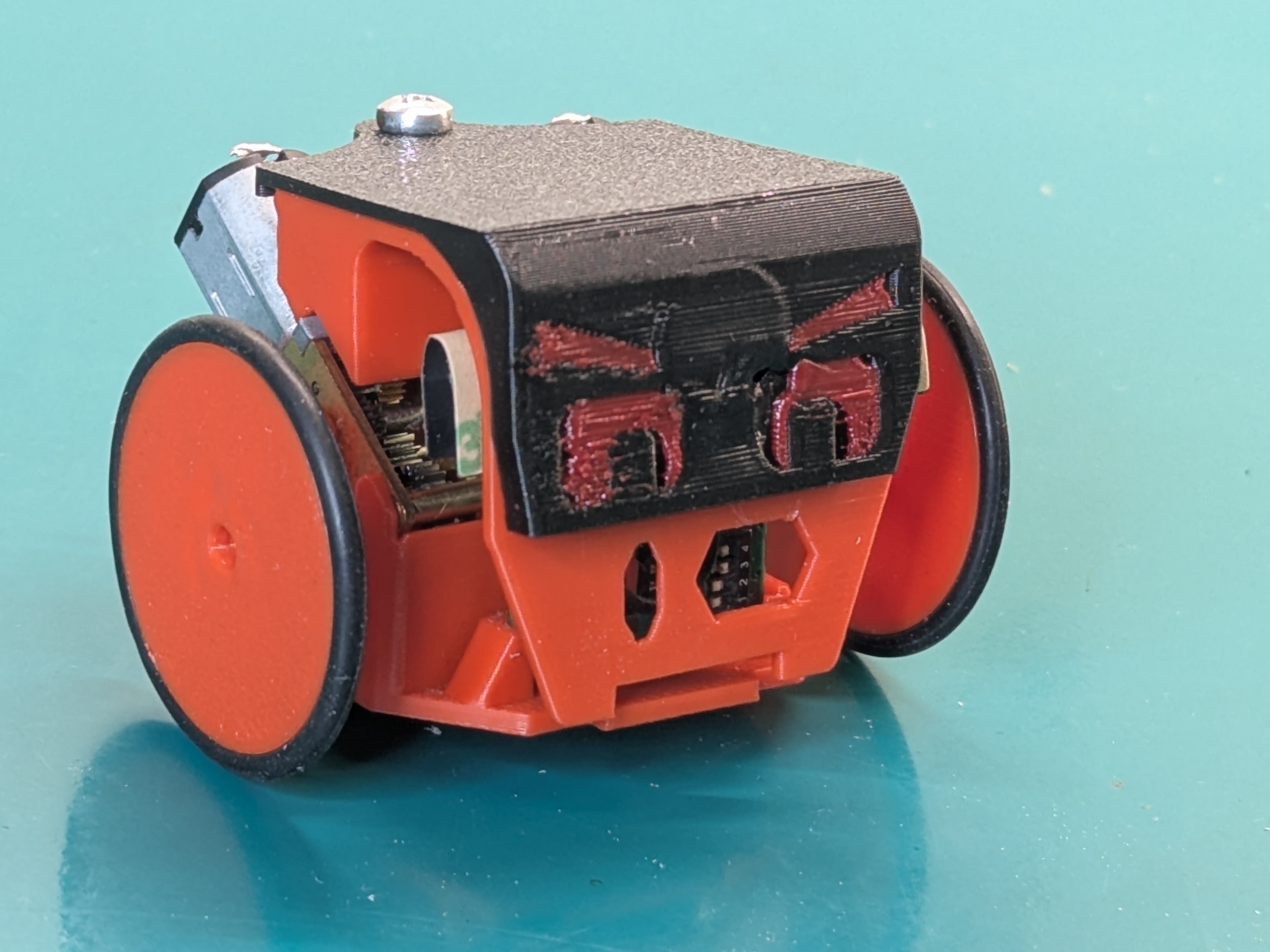
With appropriate addons, such the face-cap and the flag-backpack the speedster was able to make the BotRoyale game possible at MFR2025.
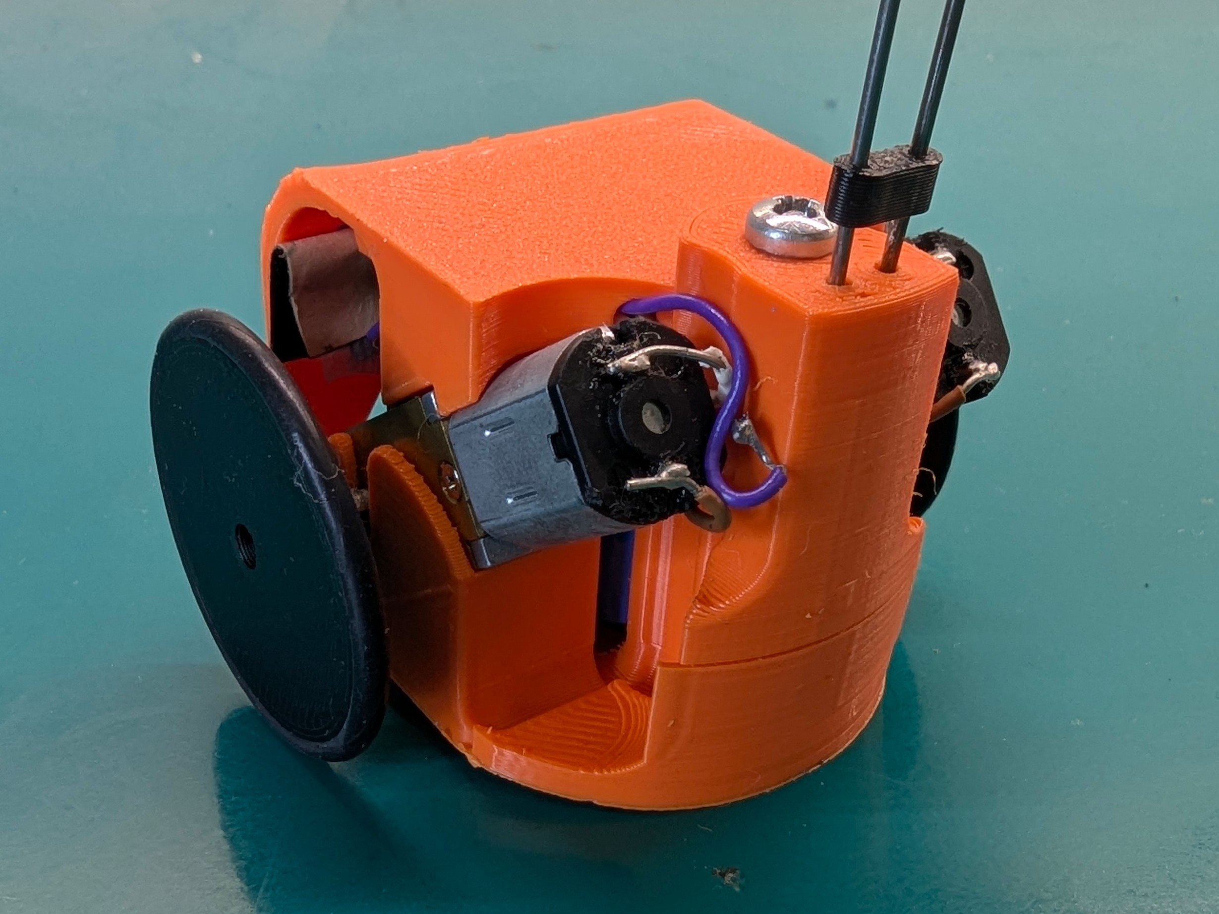
However, a few remarks, the antenna was literally forced to fit inside them and it is very annoying when you open the bot to change the battery and all the pieces start to wander around. Reason why a third generation of bots is already ready and will probably appear on this blog in the not-so-far feature.
Remote control: I2C, Wifi, BT, ESPNow
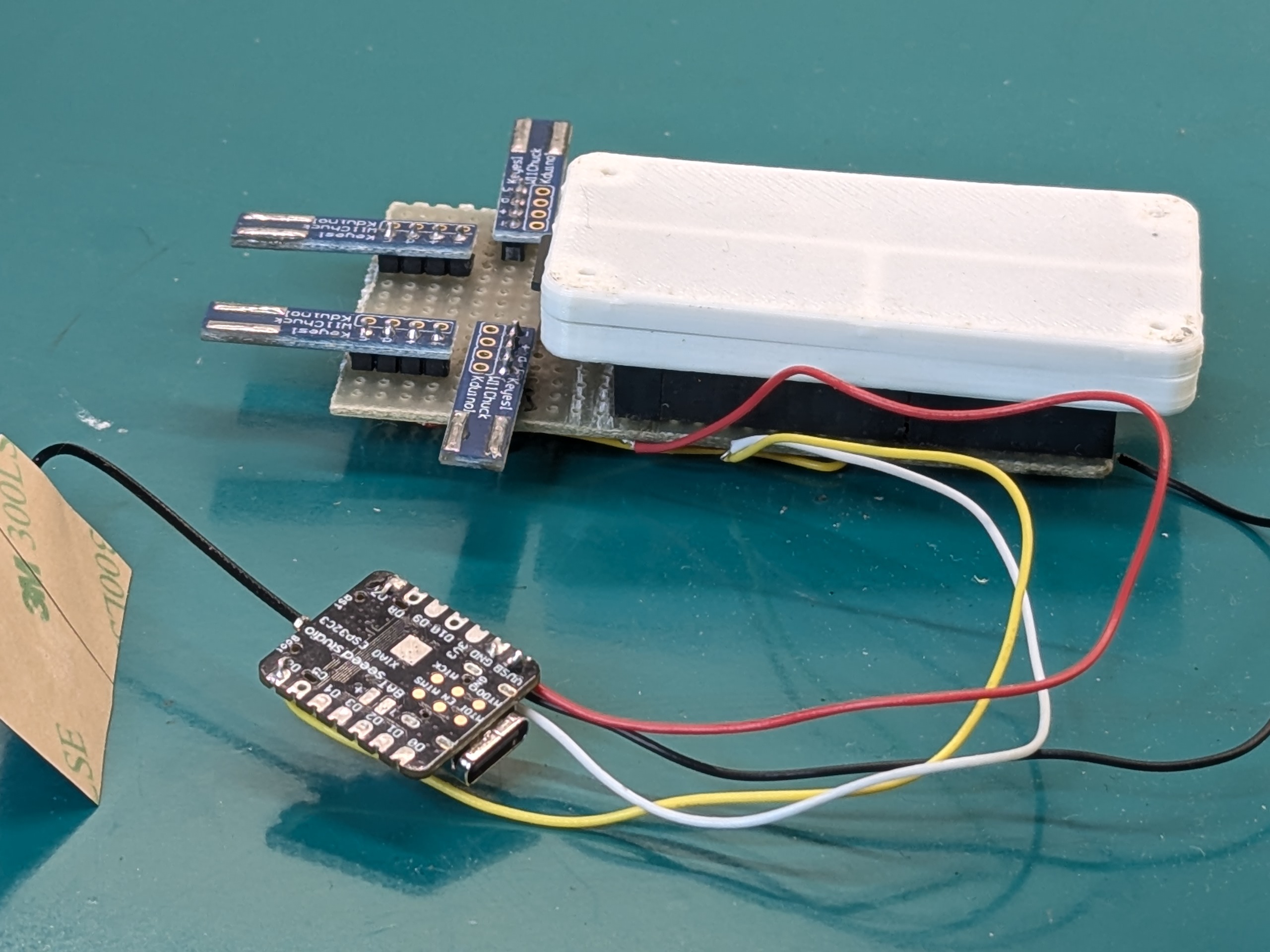
The remotes used to control the robots are good old Wii Nunchucks, the “base station” is a raspberry pi zero 2W. Since for our game we want the game state to influence how the robots move, all nunchucks are connected to the base station. Since all nunchucks have the same I2C address, I use a multiplexer to poll one at the time. I found these nice little boards on Aliexpress which plug into the nunchuck connector as breakout the I2C connectors, then I use this python library and a python script to read data from the nunchucks and forward it to the robots. The base station then runs the game logic, polls the inputs and sends the appropriate information to each robot.
The analog sticks in the nunchucks give values between 0 and 255 for each axis, plus two boolean values for the buttons C and Z. In practice, the analog sticks read a value somewhere between 50 and 200 on each axis, so I implemented a calibration routine that maps, for each joystick, the limit values on each axis to normalized values.
The nunchuks have to be polled routinely to read analog and discrete values. The sampling time matters a lot here: if it is too low the communications buffers between the station and the robots fill up, also the nunchucks have this thing were if they are probed too fast they stop responding, and communication needs to be restarted to solve it. If the sampling time is too high, there is sensible latency between command and action of the robot. This is the thing that people complained about the most during MFR2025.
As for communication between the base station and the robots, I decided against bluetooth early on, because the pairing-connection routine seemed to me way to convoluted to handle dynamically at runtime, with robots possibly changing between games, without needing to restart the base station. Also multiple robots would need to be connected to the base station at the same time, and I couldn’t find any information about either the Pi or the ESP32C3 being able to do that.
At first I tried using UDP, like I did for iFab. Even after tuning hostapd flags to reduce latency, it was still too much for the game in my opinion, but with nothing better we brought it to Botroyale.
Speaking with the guys from I Robottari at MFR2025, I was suggested to try the ESPNow protocol. It’s a proprietary protocol ESP microcontroller use, meant for low latency and low data applications. I was sold when I saw this project on hackaday using it to run 20kHz control loops wirelessly!
I implemented it after the Faire. To change as little code as possible, I added another XIAO connected the UART of the Pi itself. Now, instead of sending UDP packets to the robots, I send them in UART to the XIAO, which then uses ESPNow to send them to the other robots. The latency now is barely noticeable, and you can now actually see the play in the motors gearbox when switching driving direction quickly.
In the video we used o-rings for wheels, which seem to slip quite a lot and catch a lot of dust. We also tried casting our own from silicone rubber which was lent to us, and it seemed to slip much much less and as a result the robot would move faster. We still haven’t tried buying our own and making more extensive tests though.
Final cost
In the end, we payed 80€ for 10 shipped and partially assembled boards, 50€ for 10 XIAOs, and 70€ for 20 motors (3.5€ each). It amounts to 200€ for 10 robots, or about 20€ per single robot. This is not accounting for our own labour time and other materials like wire or solder paste which we already had.